Dårlig nyhet? Oppgradering av USB-kabel er hørbart

Diskusjonstråd Se tråd i gallerivisning

  • Bx

    Bransjeaktør
    Ble medlem
    04.08.2005
    Innlegg
    8.937
    Antall liker
    4.374
    Gatelykter er neppe det største problemet. Men hva som skjer på lysnettet kan ha betydning for lyden - spesielt om man har lineære strømforsyninger i anlegget.
     

    Midas

    Bransjeaktør
    Ble medlem
    07.01.2015
    Innlegg
    1.061
    Antall liker
    772
    Sted
    Stavangerområdet
    OT: Oppi alt dette "jeg hørte forskjell for svingende" til "jeg kan forklare at du ikke gjorde det", så må jeg si at mine tanker gjentagende gikk til diskusjonene her på forumet når jeg så filmen Red Lights av Rodrigo Cortés, Red Lights (2012) - IMDb
     

    kortvarig

    Banned
    Ble medlem
    29.04.2013
    Innlegg
    2.237
    Antall liker
    764
    Sted
    Danmark
    Hva prøver du å si med dette innlegget?
    Det er da ganske tydeligt, det er underligt form/forsøg på at gøre grin med et indlæg, nedgøre et indlæg, måske angribe indlægget for enhver pris fordi han ikke bryder sig om mig, han synes måske jeg bedrevidende eller lignede, det kunne jeg godt forestille mig, det var også årsagen til at jeg ikke gad svare. Ps. nogen gange er jeg bare vidende .

    Her er et andet eksempel på den lidt sarkastiske nedgørende stil

    Her er det så Sven Pavig som også kan være en smule alternativ som for en tur:
    "Sitat fra Sven_Palvig
    Jeg har købt fødder der leder vibrationer væk og det giver en bedre lyd. Meget bedre. Hvis det rack gør det samme, vil det vel også give en bedre lyd.

    Sigma 6 svarer: Jeg har bare købt apparater, der spiller som de skal skal fra producenten."

    Gå man igennem Sigma 6 profil vil man sikkert kunne finde en masser af den type indlæg.
    Det er den attitude en del har her på forumet , Det som jeg for ikke så lang tid siden kaldte pain in the ass.
     
    Sist redigert:

    ymir

    Hi-Fi freak
    Ble medlem
    13.12.2013
    Innlegg
    5.304
    Antall liker
    5.001
    Torget vurderinger
    2
    Oppklaring

    Skogrand sikter nok til mitt innlegg # 339 som var ett stikk til kabelskeptikkerne og dens leder,
    så da får jeg jo en anledning til å gjenta det .:)

    "Finner det ustyrtelig morsomt at blandt de som ikke hører forskjell på kabler er det en som har vert med på å utvikle kabel,som attpåtil har fått god omtale ute i den store audioverden,
    Positive Feedback Online tester Skogrand kabler
    ellers har den gjengen (følgesvennene) overhode ikke satt spor etter seg i audio historien.
    Men angripe de som virkelig har satt spor etter seg.det klarer de.Dersom de er så gode og har så mye kunnskap som de gir inntrykk av,får de komme opp med produkter som er bedre enn visse legenders,og sette sine egne spor i historien som er større en de sporene de etterlater seg en viss plass. "
     

    ymir

    Hi-Fi freak
    Ble medlem
    13.12.2013
    Innlegg
    5.304
    Antall liker
    5.001
    Torget vurderinger
    2
    Ang. gatebelysning har ikke jeg kunnet lege merke til noen åpenbar påvirkning,og det har vert satt direkte søkelys på dette hos meg.

    http://www.hifisentralen.no/forumet...643-sentralnettet-og-spenningskvalitet-2.html

    Frekvensbildet blir sammensatt. Det som har vært min antagelse er at den dominerende egenfrekvensen i seriekretsen dannet av transformatorens lekkreaktans (seriereaktans) og samlet kondensatorverdi i hele 230V nettet, muligens har ligget i området 1-2kHz. Induktansen for 315kVA transf var 21microhenry. Nødvendig kapasitans i 230V systemet for å få en egenfrekvens rundt 2000Hz blir 300 microfarad. Denne kapasitansen anså jeg som mulig når gatelyset lå innkoblet dvs. når det er mørkt. Dersom vi antar at nettet har en kapasitans på 300 microF, så vil en transformator med ytelse 800kVA gi en egenfrekvens i størrelsesorden 2600Hz.Dette kan også ses ved at transformatorytelsen er øket med en faktor på 800/315=2.5 noe som gir 1.6 ganger egenfrekvens. Samtidig øker reaktansen opp mot 1.5 og gir dermed en reduksjonsfaktor i frekvensen på 1.26. Totalt endres egenfrekvensen 1.6/1.26=1.3 dvs. 30%.


    ymir

    Hi-Fi freak
    Ble medlem
    13.12.2013
    Innlegg
    5.304
    Antall liker
    5.001
    Torget vurderinger
    2
    Dette er en bra artikkel synes jeg og den passer vel inn i en hver kabel debatt.

    Gammel men lesverdig,eller er det reklame?
    Pete Goudreau is a senior design engineer with 20 years experience in e-beam lith; ion- and electron-beam systems and source design; power-supply design; analog, digital, and RF design. He admits freely that he's "completely obsessed with audio," and this article, the first in his quarterly series on sound and engineering topics, should prove it. Expect to see articles on topics from planar speakers to passive and active preamps -- with stops in between. [HR][/HR]September 1998
    Pete's Place
    JPS Labs Superconductor Interconnects: A Technical Discussion

    by Pete Goudreau
    I can't believe it -- I'm actually discussing cables. Not being one to think much of tweaky things, I had once relegated cables to that intellectual dumpster where green ink, demagnetizers, and little wooden pucks reside under the assumption that audible differences in cables would be far too slight to be noticeable in my system. As it turns out, that assumption was wrong.
    Late last year, former SoundStage! writer Mike Fenech came to visit and brought his own cables for a comparative test in my system. To my surprise, the cables did sound distinctly different from my own, and this little incident set me to thinking about the role of signal integrity and grounding in audio systems. Turns out that the commonly held belief that only the differential-mode lumped parameters of cables (that's R, L, and C to you and me) make any difference to a cable's sonic contribution isn't all there is to consider in this application. There are the common-mode parameters of the system configuration to consider as well. These parameters, often misunderstood or ignored, play as an important, if not more important, a role than the more easily understood differential parameters.
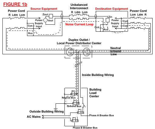
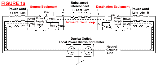
    Pro audio users and designers know well that signals carried by unbalanced cables are noisier at the receive end than they are at the transmit end; it's just a simple matter of Ohm's Law (v=iZ). Figures 1a and 1b below depict two typical ways in which signal, power, and ground become interconnected between two pieces of equipment when linked together with an unbalanced cable. The ways in which a system configuration defines interchassis potentials and thus the noise added to the signals as a function of the common-mode parameters of the interconnects and power cords aren't simple to understand, but a discussion follows in the hopes that you might gain a clearer understanding of what the average audiophile, and a good number of engineers, often considers to be black magic. Those wishing to avoid technobabble overload might want to jump ahead to the end and avoid the annoying textbook stuff that follows.
    Interchassis potentials
    Depending on the design of the equipment in question, the signal return of the connectors, which is the shell on an RCA, may be tied directly to chassis or it may be floating with respect to the chassis, as shown in Figures 1a and 1b below. Note that in the latter instance (Figure 1a) there is an impedance composed of a parallel R and C between signal return and chassis whereas in the former (Figure 1b) there is a similar impedance between chassis and neutral. It should be clear then that every signal return has an internal path to ground regardless of the detailed design of the equipment. Unless one of the pieces of equipment is battery powered, there is then a loop formed by linking the two chassis together with an unbalanced interconnect as shown in Figures 1a and 1b by the paths labeled noise current loop. Note that in Figure 1a, this loop does not contain any wiring beyond the local distribution center, whereas in Figure 1b the internal building wiring all the way back to the building load center is part of the loop.
    The noise current in this loop flows in response to an interchassis potential generated by the interaction of each chassis' differing line and neutral leakage currents with the common-mode impedance of their respective power cords. The current drawn by each power supply, through its interaction with the differential-mode impedance of its power cord and AC mains wiring, can introduce an additional interchassis potential in certain special cases. RF fields, intercepted by the loop, also generate a potential around the loop that induces an additional noise current.
    Causes
    The following discussion will center on the causes of interchassis potential, first through consideration of leakage currents and second through power-supply interactions, and the techniques by which it may be minimized. Other sources of noise currents, nonlinearities in active stages, their impact on effective noise-floor characteristics, and the unbalanced interconnect's role in converting noise current to a noise voltage are discussed in relation to interconnect design.
    The "Y" capacitors in Figures 1a and 1b, labeled Cys and Cyd, generate a leakage current that flows in the power cord's ground and neutral wires. These capacitances may or may not exist as actual parts in the equipment as the winding method of the power transformer and the power wiring in the equipment forms parasitics that would appear in the schematic in exactly the same manner. These caps are also part of any input EMI filter and add with the parasitics of the unit's construction. Designers, however, often eliminate the cap between line and chassis, as in Figure 1b, when there is no EMI filter or three-wire cord installed, or in equipment where an internal high gain stage might generate too much noise and hum. A resistor is sometimes added between neutral and chassis to form a local reference for the signal returns that are then typically connected to chassis. This added resistor, however, is occasionally left out of the design under the assumption that the destination equipment, a preamp for example, will provide the reference to ground, as in most consumer equipment. Safety is still guaranteed, however, because the open circuit potential, while high, is not dangerous owing to the high impedance of the "Y" caps that limits ground-fault current to a safe level.
    Power-supply currents, as drawn from the wall, can also create a chassis potential above ground, but only if the two "Y" caps are not of equal value, as shown in Figure 1b. A simple network analysis shows this effect to be true while also showing that if the two caps are equal, as shown in Figure 1a, the symmetry in the network causes cancellation of any chassis potential arising from power-supply input currents flowing through the power feed's differential-mode impedance.
    This differential impedance, as seen by each piece of equipment, is a series combination of its power cord and associated building-wiring impedances through which the power supply's input current circulates. The total potential induced on the chassis is then a function of the total current flowing in the building wiring between the building's load center and the local system power-distribution center (read power strip or wall outlet, etc.), and all the way back to the power company's generator terminals for that matter. This is true for the simple reason that all equipment sharing this path also generates circulating currents that add with those of the piece of equipment in question. This makes it essentially impossible for the power cord itself to make a significant reduction in the chassis potential in this instance as its impedance is nearly always smaller than the driving-point impedance presented by the AC mains. This also indicates that the AC line can only be as quiet as the noisiest source sharing the feedline. It should be noted, however, that distributed parasitics and distribution transformers in the power-delivery grid effectively act as filters that make distant noise sources less important than local ones.
    While it's possible for some line conditioners to minimize this added differential-mode noise caused by other equipment sharing the line, it's not possible to reduce significantly the driving-point impedance of the AC mains at frequencies near the line frequency without supplanting the mains themselves with a new generator source. An approximation of this technique is occasionally employed at studios through the use of a motor-generator set. A sufficiently large flywheel between the motor and the generator (an alternator actually) effectively lowers the impedance of the line while simultaneously providing filtering of noise. Some line conditioners available to the consumer attempt to attain the same effect, with varying degrees of success, generally through the use of shunting capacitance or by actively regulating the output voltage. While many conditioners contain EMI filters, these act only to reduce differential-mode, as well as common-mode, noise yet actually slightly raise the effective driving point impedance at low frequencies as the differential-mode filter components add, however slightly, to those of the AC line.
    As an aside, note that the topology of the power supply can have a strong effect on the bandwidth of the induced chassis potential only in the case where the chassis to AC mains bypass is asymmetrical. For example, tube rectifiers with choke input filters generate a more sinusoidal input current waveform, whereas solid-state rectifiers with capacitor input filters typically generate a pulsing input current waveform. This pulsing current, while inherently wider in bandwidth than the approximately sinusoidal current in the first example, will then exhibit a chassis potential tilted upward with frequency, due to the inductance of the AC feedline.
    In the special case where the chassis-to-AC-mains bypass is asymmetrical and the local power-distribution center presents a lower driving-point impedance at high frequencies than that of a given power cord, and where the equipment exhibits a wideband power-supply-input-current waveform, it may be possible to reduce somewhat the chassis potential through the use of alternate winding geometries in the power cord, such as a StarQuad arrangement. Bear in mind, however, that it is only possible to reduce the resultant chassis potential above ground by the selection of a power cord in this particular instance, but it cannot be used to eliminate it entirely. If the power-supply design is such that it does not generate a wideband current waveform, then it's unlikely that a special power cord can have much of an effect on chassis potential through its interaction with the power-supply input current.
    Balanced power
    Balanced power converters are a relatively new type of power conditioner that have come on the market in recent years and are enjoying some success in recording studios. Their use can virtually eliminate leakage and power-supply-input-current-induced chassis potentials. It does so by providing a source of power where the neutral terminal is no longer connected to ground, as it is in all unbalanced AC power installations, but to a 60V rms source which is 180 degrees out of phase with the 60Vrms source connected to the line terminal. This is accomplished with a transformer that has a center-tapped secondary exhibiting 120V rms from end to end. The center tap is connected to ground and GFCI (ground fault circuit interrupt) duplex outlets distribute the balanced power, provided by the secondary side of the transformer, to the connected equipment.
    The beauty of this arrangement is that if the "Y" caps in the equipment powered by this method are equal valued, their open-circuit center-point voltage is zero. Since this center point is connected to the chassis of the equipment, when that chassis is connected back to the ground at the center tap of the transformer, there is no potential to force current to flow. This means that all chassis connected to this source of power can have no potential difference among them, and thus there is no noise current flowing in the noise-current loops shown in Figure 1. Pretty spiffy if you ask me.
    Better yet is the simple fact that since the effective use of a balanced AC power converter mandates the use of equipment with equal-valued "Y" caps, the chassis potential then cannot be dependent on the power-supply currents drawn by the equipment. Remember that if the "Y" caps are symmetric in value, the chassis potential induced by power-supply currents interacting with the differential-mode impedance of the power feed is zero due to cancellation in the network.
    In reality, since the symmetry isn't exact, there is some residual chassis potential, but it is far smaller than it would be otherwise. This is the really killer effect of this method of power conditioning as its use not only eliminates sensitivity to the driving-point impedance of the AC mains, the topology of the power supplies, and the differential impedance of the power cords, etc., it inherently eliminates the interchassis potential that would otherwise arise when using standard unbalanced power with symmetric "Y"-cap equipment. It's the best of both worlds.
    Unfortunately, it isn't a simple matter to achieve this configuration in the real world unless the equipment designer has been careful to closely match the "Y"-cap values, including the parasitics. An Equi=Tech balanced power converter is on the list for installation in my system sometime in the future, and this will require some modification of equipment for its effective use. I'll report on its effect on sonics as well as its impact on unbalanced interconnect sensitivity at a later date.
    When standard, unbalanced power is used to power a system, however, a voltmeter can be used to reduce chassis potentials due to asymmetrical leakage currents by allowing the user to optimally orient the power-cord polarity. This is actually a useful test in that if the system noise floor seems to drop in response to power-cord polarity changes, the two "Y" caps are then usually not equal in value and often different between on and off states of the equipment to boot, making it likely unsuitable for use on balanced power. However, if the equipment has a non-medical-rated EMI filter or discrete "Y" caps of equal value, this technique will have virtually no effect on the noise floor and is therefore likely to be suited for use with balanced power. Unfortunately, orienting the polarity of the AC power plug is generally the only available method to the audiophile for reduction of interchassis potential when balanced power is not an option.
    Also, given that several sources may be connected to a preamp that may or may not bridge some or all of the input and output signal returns, the situation is decidedly more complex and even more difficult to solve or at least ameliorate in most installations. I'd bet audiophilia nervosa is not an uncommon response to some situations, especially when you throw in a connection to the cable-TV feed.
    Loop antennae, skin depths, and shields
    As if all this weren't complicated enough, every unbalanced interconnection between AC-powered pieces of equipment forms a loop antenna. Any other loop formed by any closed path along any pair of interconnects, equipment inputs or outputs, and power cords is also a loop antenna. The RF potential induced around any given loop antenna due to flux linkage causes an RF current to flow that adds to the noise current generated by interchassis potentials.
    But, the effect of skin depth is supposed to make coaxial cables immune to this problem, right? Well, sort of. While it is true that as frequency increases, the depth into the shield that the current flows decreases until essentially none of this RF noise current is flowing on the inside of the shield thus making the cable self shielding above a frequency defined by the material and construction of the shield itself. Unfortunately, some of this RF current will "leak" across the shield and induce an added noise voltage as part of the signal. This effect, known as transfer impedance in signal integrity parlance, is not only real but calculable and measurable and is of a different nature than that of the noise-current loop's effect. For calculation purposes, the transfer impedance when multiplied by the RF noise current flowing in the shield yields the noise voltage added to the signal. Thus the transfer impedance should be as low as possible over as wide a frequency range as possible.
    Transfer impedance is fundamentally a measurement of the external field that gets coupled across the boundary of the shield into the signal path itself. The physical properties and geometric configuration of the shield controls the magnitude of this effect. The difference is more obvious though at high frequencies (>1MHz to 10MHz) where the shield's mutual inductance becomes the dominant source of signal coupling. Interestingly, the transfer impedance rises with frequency above this point for virtually all shield constructions with the exception of a solid-copper shield such as that found in the JPS Labs Superconductor interconnect.
    As an example, spiral and folded aluminum foil shields have a rather high transfer impedance in comparison to nearly all other types. A braided copper shield is better and can be optimized through proper selection of strand diameter, grouping, optical coverage, and crossover angle, as well as the material properties themselves. Even when optimized, though, the transfer impedance reaches a minimum in the 1MHz to 10MHz region and climbs inductively beyond this, not to mention that it is significantly increased when the cable is formed to a radius, etc. Concentric braided shields perform slightly better, but the very small parasitics formed by the radial and longitudinal gaps inherent in their construction results in a severe ripple in the transfer-impedance curve with minimums tangent to the ideal inductive response.
    A solid copper shield on the other hand drops in magnitude through the 1MHz to 10MHz region, exhibits no minimum, and no subsequent inductive rise below several hundred megahertz. Thus the transfer impedance of a solid copper shield can be as much as 20 to 30dB lower than that of an optimized braided copper shield at 10MHz, and as much as 100dB lower at 50MHz . At lower frequencies, though, it is possible for the braid to have a lower transfer impedance than a solid copper shield unless the solid shield is made thick enough to provide an equivalent bulk resistance as is done in the Superconductor interconnect.
    Consider also in this context that the clock frequencies in transports, CD players, and outboard DACs are at either 16.9344MHz or 11.2896MHz, for 44.1ksps data, and that the clocks are generated with CMOS logic having rise times in the 2ns to 7ns range, and it is easy to see that the spectral content extends well beyond 100MHz since the first break in the fourier series for a trapezoidal waveform is at 1/pi*tr. Additionally, radiation efficiency of E field emissions rises at 20dB/decade and at 40dB/decade for H field emissions, making the near-field coupling of sources at these frequencies surprisingly strong since the near field for 100MHz extends easily to a few feet in space from the radiator. When you consider the fact that few pieces of equipment are designed to minimize their near-field emissions, it isn't too surprising that EMI pickup from digital audio equipment can easily find its way into every other piece of equipment in the system purely from radiative coupling effects.
    The JPS Labs Superconductors
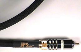
    The Superconductor interconnects ($295 USD per pair) use a thick, solid copper shield that not only provides a very low resistive return path but a very low transfer impedance as well that continues to drop in magnitude with increasing frequency in exactly the frequency range where it is most critical to do so, unlike the more common braided shield constructions found in other cables. This makes its use as an analog interconnect much more useful in reducing the effects of coupled RF in conjunction with equipment that may not be designed to deal adequately with it. This is a rather gross oversimplification of the problem, after all the aperture coupling effects at the RCA connectors and the RF-current paths through and across the surfaces of the equipment wasn't discussed, so we'll leave it at that for the moment as some are likely wondering how the hell RF makes a difference in audio signal transfer anyway. Well, there's that spectral contamination problem.
    You see, there's no such thing as a perfectly linear amplifier, or resistor for that matter. At some frequency or amplitude, nonlinearity exists at a magnitude that makes for some interesting effects. A nonlinear element in the signal path is going to create signals where there were none before. This isn't to say that something is created out of nothing, only that the signal energy is redistributed to the "new" signals, in passive nonlinearities anyway, to be more precise. The upshot of this technobabble is that no matter how clean the signal is when it comes into a piece of equipment, it can't be as clean coming out.
    One of the more germane aspects of nonlinearities is that if there are two perfect sine waves at two different frequencies going in, there will be sine waves at the sum and difference of their two frequencies coming out in addition to other distortion products. This is known as intermodulation. If these two frequencies going in are high-frequency noise, and that high-frequency noise is at frequencies where the internal circuitry is nonlinear, their distortion products end up in the audio band even if they weren't there to begin with. This is but one example of spectral contamination; ultrasonic and RF energy that finds its way into the circuitry can also cause other problems such as offsets, intrastage overloads, demodulation products, noise modulation, etc. The entire range of nonlinearity-related error is referred to as spectral contamination and is measurable through known techniques.
    RF and cables
    Well, what does all this power-line and RF stuff have to do with cables? Good question, and here's the answer -- about time too.
    Given the simple fact that an unbalanced cable linking two ground referenced pieces of equipment forms a loop and that since there must exist a potential difference around the loop due to chassis leakage and possibly power-supply currents, as well as intercepted RF flux, a noise current then flows. The return impedance (the common-mode impedance) of the interconnect converts this noise current to a noise voltage, at low frequencies, that adds to the signal voltage at the destination equipment, and the transfer impedance of the cable allows some of the induced RF current to superimpose a frequency dependent RF noise voltage on the signal. Spectral contamination will convert the higher-frequency components of this noise voltage to inband distortion products while the lower-frequency power-supply-related components will simply be amplified as inband components. Thus the common-mode and transfer-impedance characteristics of an unbalanced interconnect can directly affect the noise floor of the signal as processed by the destination equipment. Note that these two impedances are but two sides of the same coin, rather than two completely unrelated parameters, and the overall effect is bit easier to understand.
    Now, again, the observant reader is probably asking how this RF noise can get into the circuit in the first place. Isn't that what filters and stuff like that are for? Sure, you bet -- shame it's rarely done correctly though. Just because the schematic says there's a filter there doesn't mean that it works like one over the range of frequencies where noise is likely is get into the system due to chassis design and other EMC (electromagnetic compliance) considerations. Component parasitics that alter the filter response at high frequencies, radiative coupling across the filter, etc., usually defeat the best laid plans of the designer. In reality, all equipment exhibits, to some degree, conducted and radiated susceptibility to EMI/RFI.
    Conducted susceptibility is the lack of the ability of the input-stage-cable termination and filter design to adequately reject or filter out signals that might result in abnormal operation of the signal-processing circuitry. The actual design of the signal-processing circuitry itself is often important in this regard as well -- e.g., suppressed high-frequency gain in the first stage, elimination of miller integrator compensation stages, the use of folded cascode gain stages, careful shielding between stages, board-layout techniques that suppress common-mode signal flow through differential-mode signal paths, etc. Unfortunately, all of these are under the control of the equipment designer and cannot be addressed by the choice of interconnect.
    Radiated susceptibility is the lack of the ability of the enclosure and the input- and output-connector-return bypasses to shunt these high-frequency noise currents, riding on the outside of the shield, away from the signal-processing circuits located inside the chassis. The noise voltage induced by these currents is usually expressed as the transfer impedance of the cable termination and is typically added with the cable's transfer impedance in order to express the overall transfer impedance of the signal path. Note that the cable termination's transfer impedance is controlled only by the design of the equipment and cannot be reduced through reduction of the cable's transfer impedance.
    With the advent of digital equipment, this problem can be many times worse than it ever was with phono equipment, concerning local generation of EMI as detailed earlier, as opposed to the problem of designing and packaging a very high-gain-stage amplifier to reject low-level ambient RFI. In other words, today's home listening environment is not as benign as it once was, so it should come as little surprise that an unbalanced interconnect can sound different on different equipment and in different systems. Thus it behooves the user to choose an interconnect that provides as much immunity to EMI/RFI as possible in order to minimize its impact on equipment of unknown design quality.
     

    Steinar_Lund

    Hi-Fi freak
    Ble medlem
    17.03.2002
    Innlegg
    7.813
    Antall liker
    2.736
    Sted
    Hvalstad, Asker
    Torget vurderinger
    3

    ymir

    Hi-Fi freak
    Ble medlem
    13.12.2013
    Innlegg
    5.304
    Antall liker
    5.001
    Torget vurderinger
    2
    Is it audible?
    OK, so your equipment is impeccably designed for RFI rejection (it says so right here in the fine print of your bank balance) and the only noise of any concern is then that due to interchassis potential. The question then becomes whether or not this whole mess is even audible in the first place. And therein hangs a tale.
    I, for one, never considered this much of a problem as it's just so obvious that the noise must be so small that it can't possibly be heard in a normal listening environment at normal listening levels, right? Well, not so fast, it turns out life just isn't this simple after all (did he say simple?!). There's this little matter of common-mode resonances in the interconnection that just didn't get mentioned in too much detail above but the reader who is an electrical engineer will likely have clued into the fact that the loops discussed above are a series and parallel combinations of R, L, and C and that means resonances where the loss in the loop (the R) controls the Q of those resonances.
    Figure 1a shows a configuration that is not uncommon with a digital source. The Noise Current Loop drawn in the picture is the mesh to solve for the noise voltage that appears across the return path of the interconnect as a function of the interchassis potential. The solution of this mesh indicates that either Rcs or Rcd, or both depending on relative values, controls the Q of the resultant voltage divider with smaller values contributing to a lower Q. Note that in Figure 1b, the loop is a different topology but its solution is effectively identical. This indicates that lifting the earth of the power cord might make an audible difference but it can't eliminate the problem entirely.
    At high frequencies though, the loop can be viewed as a simple inductive voltage divider. This means that the ultimate rejection of the noise potential driving the loop is a direct function of the ratio of the common-mode impedances of the interconnect and the power cords. Since the common-mode impedance of a power cord is usually quite low, it is critical then that the common-mode impedance of the interconnect be as low as possible in order to minimize noise in the unbalanced signal. This remains true regardless of the damping in the loop. It should be noted at this point that in reality, the return path impedance of the interconnect contains the contact resistance of the connectors as well. Since the resistances involved are quite small, the contact resistance then becomes a critical issue as well. The use of locking RCAs then seems mandatory in this context.
    Additionally, it seems reasonable that instead of attempting to reduce the common-mode inductance of the interconnect below that of the power cord, measures could be taken to increase the common-mode impedance of the power cord with ferrite beads or the like. While this makes sense based on the math of the solution, adding ferrite beads to the power cord should be approached with caution as they act much like an inductor in parallel with a resistor. The inductance due to an unwise choice of bead type can be such that the resonant frequency of the loop is then shifted down in frequency closer to the audio band thus making damping of the loop more critical in avoiding spectral contamination effects. While adding beads to the power cord can be a touchy operation, it is by far more preferable than adding them to the interconnect and often a suitable adjunct to reducing the common-mode impedance of the interconnect.
    Ferrite beads are however often the only effective way to reduce the RF noise current induced in any loop antenna. Since adding ferrite beads to the interconnects has been shown in the preceding paragraphs to be unwise, the best approach here is to place beads on the power cords that are as lossy as possible at as low a frequency as possible with as low an inductance as possible so that low frequency damping characteristics of the loop are not compromised. This set of parameters is discernible only through evaluation of the impedance curves for any given bead and the relation of that impedance to that of the power cord. Unfortunately that information is rarely available to the consumer making the application more of a crap shoot than it would first seem. It is possible though to experimentally find a bead and power cord pair that can reduce the overall noise floor in the system but the user should bear in mind that if it makes a significant difference, the source of RF that the bead is working against is most likely being generated locally in the system and that the correct solution is to stop the noise at its source rather than trying to filter it out somewhere else. This comes down to locating the source and either modifying or removing it from the system. Minimization of the EMI emissions from any given piece of equipment is however entirely the responsibility of the designer and not the user.
    Note also that the loop antennae formed by pairs of interconnects between chassis in the system cannot be treated in this manner since it would require placing beads only on the interconnects and this would raise the common-mode impedance of the interconnect itself, thus actually increasing noise in the signal due to the noise current flowing in the main Noise Current Loop. Thus, the only way to reduce RF-related noise riding the signals in these loops is to make certain that the transfer impedance of the interconnects is as low as possible and that the equipment is designed for minimal conducted and radiated susceptibility as well as minimal spectral contamination. The clever reader will see that simply making a twisted pair out of the two interconnects would strongly reduce the RF-noise current flowing in that particular loop, and that would be correct. It isn't perfect, and it might not work in all systems, but it is far more preferable than adding ferrite beads to the interconnects.
    Since so little equipment is designed to take this effect into account, at least from the limited number of pieces of equipment that I've seen over the years, a high Q resonance can exist that causes a peaking of the noise voltage in the ultrasonic to low RF frequencies making it much more difficult to filter out the noise at the destination end, thus increasing the likelihood of spectral contamination in the destination equipment's circuitry. The point is that direct reduction of spectral contamination cannot be accomplished through the choice of interconnect alone, it is a function of the interaction of the interconnects, the power cords, and the equipment design. However, it is possible to minimize the effect through a judicious choice of the first two items along with an optimal selection of ferrite beads. Again, as with EMI emissions, elimination of spectral contamination is ultimately the responsibility of the equipment designer.
    Back to the Superconductors
    The Superconductor interconnects have an extremely low return path impedance, aided by the use of locking WBT-like RCAs, which seems to work well in minimizing the effects of spectral contamination and direct noise current conversion. Since the return path impedance is so low, it is likely to make the issue of common-mode resonances in most systems a moot point as well. This can be a nice benefit for most users as it is quite a bit cheaper to replace interconnects than equipment. The user also is spared the pain and agony of attempting to understand the arcane field of common-mode network analysis in order to make rational modifications to their equipment, although in reality modifications of this nature couldn't hurt. Considering the labor necessary to terminate this type of cable, I consider the choice by JPS Labs to use the locking WBT-like RCAs a wise one and well worth the incremental cost of the interconnects in my estimation. I suppose it is also possible that the tighter compression fit of the locking RCAs might also serve to minimize point contact oxidation effects without resorting to heavy molecular weight contact enhancers, etc., but that is a minor point I think.
    Some months ago, prior to working through these issues and equations, I had replaced the Monster wiring in some old M350i cables that I had been using with some Canare GS6 cable that seemed reasonable for use with unbalanced signals based on an assumption I made about the shielding effectiveness and the differential mode lumped parameters. It was a significant improvement in my system, the magnitude of which I didn't honestly expect. Now it seems plausible that the twisted-pair construction of the M350i, which has a rather large impedance in the return path when compared to that of coax like the GS6, might easily have been responsible for the noticeably smoother and more pleasant sound the change produced. There was also a clearly audible decrease in glare and haze that I typically associate with a reduction of RFI in the system. Consideration of the common-mode parameters of cable construction now seems like the only rational explanation for the distinct difference in sound between the two cable construction methods, at least to me.
    Sound thinking
    After this little experiment, which prodded more work on the analysis presented here, it seemed rational to investigate different ways to achieve even lower return-impedance methods of cable construction in order to find out if it could make a difference again. Since the system sounded pretty good at the time, I didn't pursue it very strongly until I stumbled across the JPS Labs Superconductor cables. The literature seemed to indicate that they would be even better than the GS6 in terms of common-mode parameters as well as transfer impedance, so they seemed like they'd be worth a shot.
    The differences as I heard them then and now? A much greater sense of presence and clarity, verging on crystalline in their presentation of the upper octaves, was immediately noticeable, making it seem as if the GS6 cables were as bad in comparison with the JPS as the Monster was in comparison with the GS6. The ease with which the music flowed is of a character that didn't exist emotionally with me to this degree before the change in cables. I must admit that I wasn't prepared for such a dramatic change, and it wasn't just me. My wife, not knowing anything about the change at the time, noticed the sound differences immediately and expressed that it was as if the system were transformed in terms of its quietness. She felt that a layer of noise had been wiped away that apparently wasn't noticeable before. It was noise that seemed always to be part of the sound yet not part of the sound, making it quite difficult to explain, but the effect was clear to both of us. Without any coaching or discussion, she had come to the same conclusions I had using the same words I was thinking. It seemed sufficiently conclusive for me.
    During the following days, I took pains to perform comparisons with the GS6 cables as best I could and it did seem as if the noise floor were dramatically lower with the JPS cables. I spent a few weeks looking for a downside to all of this and simply couldn't find one. While the sound was amazingly transparent, there was no evidence of glare, haze, smearing, edginess, brightness, or anything else that would induce listening fatigue. The upper octaves seemed so much more lifelike and relaxed, for lack of a better choice of words. Peculiar that such a change could cause such a change. Then again the math says this must be true if the noise level, and the resultant spectral contamination, were indeed audible, which this series of tests, and I use the word loosely here, tends to indicate.
    The real kicker though was the improvement, subtle as it was, in the sense of space and depth as well as the improvement in imaging specificity. Bells, cymbals, etc. don't sit on the speaker baffles anymore, but float freely in space, immediate and realistically detailed and as airy as anything I've heard shy of live. That sense of perspective and the ease with which the upper octaves seem to bloom without any hint of artifice contributes greatly to the beauty of the music in my estimation, and it simply didn't exist prior to the installation of the Superconductors. I must admit to being dumbfounded by the changes wrought by these cables. At first, I naturally assumed that the mere act of changing the cables out was sufficient to clean the contact surfaces, but care was taken to clean the contacts with 1,1,1 TCE between changes so as to minimize the possibility that perhaps some contaminant on one or the other might be responsible for perceived differences. Regardless, the choice was obvious and unanimous that the Superconductors were more pleasant and realistic to listen to -- if only by a small margin in absolute terms, but by a wide margin in subjective terms. In a related set of tests, the GS6 cables were essentially unlistenable in contrast to either.
    I should also mention that prior to receiving the Superconductor cables for review I installed a homemade active isolator box to break the ground loop generated by connecting the TV/VCR feed to the passive controller. This allowed the cable feed to be connected directly to the wall and that provided the earth connection for the VCR, an important consideration as it's a dirty chassis design. Prior to this change, the VCR's floating chassis (54V rms open circuit) found its way to ground through the commoned returns on the passive controller and through the low-impedance signal return to chassis bypass of the DAC -- quite a serious case of noise current if you ask me. At the same time, my Krell KSA-150 chassis could then be grounded without the excessive hum otherwise created prior to this installation. Overall system sonics were improved considerably in the process, and the noise level in the system seemed to drop dramatically as well. Yet with all the reduction in interchassis potentials afforded by this change, the JPS type interconnects still made a clearly audible difference. Again, it seems the only way to eliminate the problem of noise in unbalanced interconnects entirely is the application of balanced power. But would this mean that the use of balanced power would obviate the differences in unbalanced interconnects?
    Well, there is one other source of noise that all cables exhibit to one degree or another, and that is triboelectric noise. That's noise generated by friction between conductors and dielectrics and between dielectrics and fillers, for example. This noise is also a function of the materials themselves. The Superconductor cables are built such that the dielectric is bonded to both the center conductor and the shield. Thus there can be no relative movement, so there is no friction generated and no triboelectric noise. The materials used, copper and foamed polyethylene, are two of the lowest triboelectric generators available as well. I suspect, but can't prove, that this might also be another source of the improved clarity of sound over that of the GS6 which uses the common technique of serving a conductive nylon tape between the shield braid and the dielectric to drain off the triboelectric charge induced by vibration and flexing, apparently not effectively enough though compared to the construction techniques of the Superconductor cables.
    Since the destination input impedance is rather high in most installations, this is not something to be dismissed entirely and again is an effect well known among cable manufacturers, especially for high-impedance sources and those requiring high-gain amplification. Does it apply to high-level line signals? Possibly, but I couldn't tell you for sure. Instead, the construction of the Superconductor interconnects eliminates this problem entirely, yet does not add significantly to the cost of the finished interconnects. Thus, to my mind, another source of worry is simply removed free of charge. Sorry about that -- don't you just hate a bad pun?
    Findings
    Regardless, in terms of purely technical issues, the Superconductor interconnects seem to meet all the requirements laid out so far and are built quite well to boot. My conclusion is that the combination of very low return impedance, low transfer impedance, and bonded dielectric seems like it would be of great benefit in keeping the noise floor as low as possible in an unbalanced interconnect when used in most any system.
    The very low capacitance and inductance of the cables are not unimportant as well, especially for use with passive controllers. At about 25pF/ft, these cables are about half as capacitive as the GS6 cables. While this may have something to do with the sound differences, the rolloff difference is totally negligible in my system with a source resistance of about 75 ohms in the DAC and a maximum of 1k ohms in the passive controller with most listening done with an output resistance below 200 ohms. DAC to passive length is 0.5m and the passive to amp length is 1m, making the capacitive loading of the cable negligible in context. It is hard to imagine that such a small change in capacitive loading could cause such an easily perceived difference in sound quality. Thus my above conclusions relative to common-mode impedance, transfer impedance, and triboelectric noise instead.
    Bottom line? I'm keeping 'em and will likely buy another set for the tuner and TV/VCR isolator feed paths as well. Returning to the GS6 interconnects after this more extended period is quite disappointing now and clearly inferior, even more so than during the initial comparison testing where the cables were swapped in and out of the system over the span of several days. The clarity and precision of presentation with the Superconductor interconnects is quite addictive, and I can't recommend them enough if your system components tend toward neutrality or warmth. I would suspect that a naturally bright system would be exposed by these cables for the pain that it usually is, whereas a competently assembled system should shine even brighter with their use. If you find these cables to be unnatural-sounding, I would suspect that the components are either overly bright in their character, or there is some other source of error in the system that these cables are merely bringing to your attention.
    There may be better interconnects available to the consumer, but frankly I'm hard pressed to imagine what they might be or how they could be better. And the cost is low enough to make the Superconductors one hell of a bargain compared to a lot of the truly high-priced stuff out there vying for your dollar. Give 'em a try. I'd be amazed if you weren't
     

    ymir

    Hi-Fi freak
    Ble medlem
    13.12.2013
    Innlegg
    5.304
    Antall liker
    5.001
    Torget vurderinger
    2
    Går og grubler på dette for tiden

    http://www.hifisentralen.no/forumet...43-sentralnettet-og-spenningskvalitet-15.html

    Noen utdrag fra artikkelen + litt fra ett intervju med John Curl


    Grubler fordi noe av kablingen min tror jeg har aluminium viklet rundt som skjærm,

    og at preamp og DAC har ringkjerne.

    But, the effect of skin depth is supposed to make coaxial cables immune to this problem, right? Well, sort of.

    spiral and folded aluminum foil shields have a rather high transfer impedance in comparison to nearly all other types

    it isn't too surprising that EMI pickup from digital audio equipment can easily find its way into every other piece of equipment in the system purely from radiative coupling effects.

    wondering how the hell RF makes a difference in audio signal transfer anyway.

    there's no such thing as a perfectly linear amplifier, or resistor for that matter. At some frequency or amplitude, nonlinearity exists at a magnitude that makes for some interesting effects

    no matter how clean the signal is when it comes into a piece of equipment, it can't be as clean coming out
    One of the more germane aspects of nonlinearities is that if there are two perfect sine waves at two different frequencies going in, there will be sine waves at the sum and difference of their two frequencies coming out in addition to other distortion products. This is known as intermodulation. If these two frequencies going in are high-frequency noise, and that high-frequency noise is at frequencies where the internal circuitry is nonlinear, their distortion products end up in the audio band even if they weren't there to begin with. This is but one example of spectral contamination; ultrasonic and RF energy that finds its way into the circuitry can also cause other problems such as offsets, intrastage overloads, demodulation products, noise modulation, etc. The entire range of nonlinearity-related error is referred to as spectral contamination and is measurable through known techniques.


    The point is that direct reduction of spectral contamination cannot be accomplished through the choice of interconnect alone, it is a function of the interaction of the interconnects, the power cords, and the equipment design


    INTERMODULASJON og HIFI er noe dritt.

    https://nn.wikipedia.org/wiki/Otalaforsterkaren
    førte ofte til at lyden fekk ei hard «metallisk» klangfarge


    Sitat John Curl

    "AC power is so dirty.
    Harmonics that are created by high frequency fluorescent lights, fax
    machines, computers, you name it. All this new stuff, that’s only been
    around for maybe the last 10 years, tends to get into the power supply
    through the transformer and then in to he grounding system and
    ultimately into our sound system"
     

    jane

    Hi-Fi freak
    Ble medlem
    27.06.2004
    Innlegg
    3.108
    Antall liker
    1.117
    Sted
    '
    INTERMODULASJON og HIFI er noe dritt.
    Nå blander du sammen begreper og konklusjoner.

    Du påstår: IMTERMODULASJON og HIFI er noe dritt.

    For å underbygge denne påstanden viser du til «Noen mener TIM ofte førte til hald/metallisk klang» som du finner i en Wiki-artikkel om TIM.

    TIM har en annen årsak og ikke er det samme som Intermodulasjon (IM).

    Påstanden din underbygges av feil i argumentasjon og er sånn sett ikke gyldig.
     

    ymir

    Hi-Fi freak
    Ble medlem
    13.12.2013
    Innlegg
    5.304
    Antall liker
    5.001
    Torget vurderinger
    2
    INTERMODULASJON og HIFI er noe dritt.
    Nå blander du sammen begreper og konklusjoner.

    Du påstår: IMTERMODULASJON og HIFI er noe dritt.

    For å underbygge denne påstanden viser du til «Noen mener TIM ofte førte til hald/metallisk klang» som du finner i en Wiki-artikkel om TIM.

    TIM har en annen årsak og ikke er det samme som Intermodulasjon (IM).

    Påstanden din underbygges av feil i argumentasjon og er sånn sett ikke gyldig.
    Denne "noen" er jo Ottala.....og det er ikke søkt på TIM i Wiki men Ottala.

    Ellers er mitt poeng at intermodulasjon,om det er TIM eller annen form for intermodulasjon kan gi den samme subjektive lytteopplevelse,"hard/metallisk klang"

    TIM
    Transient Intermodulasjon og intermodulasjon er forvrengningskomponenter som går under ikkeharmoniske. Disse måles da separat, men denne igjen kan også deles slik at man får isolert den delen som er hørbar fra den ikke hørbare.
     

    kortvarig

    Banned
    Ble medlem
    29.04.2013
    Innlegg
    2.237
    Antall liker
    764
    Sted
    Danmark
    @Ymir det var en ordentlig smører vi fik der, men jeg mener stadigvæk ikke at det har noget med det "mystiske" at gøre.

    Det jeg først lægger mærker er at indlægget er en stor smart skjult reklame for JPS labs kabler, det er nok for mig til at står af. (en såkaldt se hvor dygtige og seriøse vi er reklame, meget benyttet marketing-tricks, og vi har tilfældigvis lige fundet den tekniske løsning på problemet.

    Men ret skal være ret meget af det der står er helt korrekt og almindelig kendt viden blandt elektronikfolk og det der nævnes har naturligvis en betydning som typisk vil resulterer at kablernes klang bliver afhængige af den aktuelle konstruktion, og det er netop det som ikke!!!! sker.

    Elektronik er indviklet og som artiklen også påpeger, der skabes fejlpotentialer, lækstrømme, fejlkondensatorer, bl.a. i forhold til chassiset, der er fejlspoler , fejlmodstande, variable kontakt-modstande stik/bøsninger, og alle disse komponenter skaber bl.a. også fejlresonanser , listen er lang, der er usynlige fejlkomponenter som ikke er en del af konstruktionen over alt i vores apparater, som er med til at generer fejl, skjulte komponenter som man bør være opmærksom på , og forsøge at minimerer, og om ikke andet lave disse fejlkomponenter så "gode" som det er muligt.

    Alt dette er med til at påvirker performers hvad angår IM forvrængning støj ,fejlresonanser osv, og alt dette bliver langt mere kritisk jo højre frekvensen er, det er der slet ingen tvivl om. Jeg har som sagt arbejdet med højfrekvens i flere år.

    Af samme grund bruger jeg ikke selv chassis, og jeg bruger batteridrift, og jeg bruger ikke stik og bøsninger, og mit stel-layout og kabler er med litzetråd (for at sikre så lav modstand for Højfrekvens som muligt samtidig med at jeg kan få et fornuftig kvadrat lav modstand).
    Stelplan er lagt så clean og simpelt ud som det muligt. Jeg er Diy mand og skal ikke tage hensyn til noget, pris , udsende, produktions forhold osv. jeg kan bare lave det så godt som muligt.

    Men mærkeligt er det , der er stadigvæk de samme forskelle på kabler og passive komponenter generelt, ja faktisk er forskellene mere tydelige end ved traditionel konstruktion, måske fordi det ikke bliver maskeret af alt den støj og resonanser IM osv som er resultatet det denne Pete taler om i artiklen.
    Når jeg måler eller ligger øret helt ind i så er der intet støj der er tavst som i graven, men selv om der havde været lidt støj så er det ikke forklaringen på det mystiske.

    Havde denne Pete prøvet at bygge to helt identiske konstruktioner, hvad angår stelveje , chassis, og strømforsyning, og bare havde valgt at bruge en anden type modstand eller kondensator i den ene konstruktion, så havde han kunnet opleve/høre større elle mindre lydmæsig forskel, ja han havde kunnet opleve/høre overaskende stor forskel, som Paul McGovan fra PS Audio forklarer her: http://www.hifisentralen.no/forumet...-av-usb-kabel-er-ha-rbart-17.html#post2152929

    Det er faktisk rigeligt at udskifte en enkelt modstand af de i forvejen hundredvis som sider der i forvejen, eller sågar bare at udskifte komponent-benene fra kobber til finsølv på en enkelt modstand , eller en kondensator, man kan evt kompenserer for finsølvs bedre ledeevne hvis man vil det, det gør absolut ingen forskel overhovedet.

    Så kan vi jo se om denne Pete kan måle dette, og ikke mindst forklarer den markante lydforskel, som bare er en anden klang ,det er ikke støj ,eller forvrængning, den ene klang kan i princippet være lige så god som den anden.
    Personligt mener jeg bare at finsølvs klang harmonerer bedre med hvordan instrumenter lyder live , så det vælger jeg, men jeg kunne lige så godt have valgt kobbers klang, der er umiddelbart ingen forvrængning i kobber hvis det er rent, der er bare en anden klang i kobber i forhold til finsølv, Ps der er naturligvis heller ikke forvrængning i finsølv.
     
    Sist redigert:

    I_L

    Hi-Fi freak
    Ble medlem
    27.03.2003
    Innlegg
    3.343
    Antall liker
    5.443
    Leste ikke den lange utlegningen, men TIM er det samme som slewing og har ikke noe med det andre å gjøre. Slewing forekommer heller ikke i kabler.
     

    Aurora

    Æresmedlem
    Ble medlem
    04.06.2004
    Innlegg
    15.328
    Antall liker
    11.869
    Sted
    Ytterst i havgapet...
    Otalas arbeider med TIM har, kort fortalt, sitt utspring i det faktum at de store effekttrinnene som kom på slutten av 60 tallet målte etter datidens standard fantastiske THD verdier under statiske betingelser, men låt astrengt og slitsomt. Forklaringen lå i datidens effekttransistorer, som hadde svært begrenset båndbredde, og derfor ble "impulsmessig overstyrt" av mye raskere inngangs- og drivertrinn, derav navnet Transient IM. Derav følger også noe av dagens designkriterier med lokal begrensing av båndbredden i tidlige trinn.
     

    I_L

    Hi-Fi freak
    Ble medlem
    27.03.2003
    Innlegg
    3.343
    Antall liker
    5.443
    Skogrand sikter nok til mitt innlegg # 339 som var ett stikk til kabelskeptikkerne og dens leder,
    så da får jeg jo en anledning til å gjenta det .:)

    "Finner det ustyrtelig morsomt at blandt de som ikke hører forskjell på kabler er det en som har vert med på å utvikle kabel,som attpåtil har fått god omtale ute i den store audioverden,
    Positive Feedback Online tester Skogrand kabler
    ellers har den gjengen (følgesvennene) overhode ikke satt spor etter seg i audio historien.
    Men angripe de som virkelig har satt spor etter seg.det klarer de.Dersom de er så gode og har så mye kunnskap som de gir inntrykk av,får de komme opp med produkter som er bedre enn visse legenders,og sette sine egne spor i historien som er større en de sporene de etterlater seg en viss plass. "
    De du henviser til som legender i hifi-miljøet er stort sett no-names i elektronikkmijøet generelt. "Legendene" i elektronikkverdenen heter Gordon Moore, Bob Widlar eller Gabor Temes, ikke Noel Lee eller Uri Geller. Hvis du vil ha en sterk CV som elektronikkutvikler har du et vitnemål fra et respektert universitetet, og hvis du har refererte/siterte publikasjoner i IEEE (Institute of Electrical and Electronics Engineers) i tillegg er dørene ganske åpne. Og hvis du blir IEEE Fellow begynner vi å snakke om faglig berømmelse.

    Det totale bidraget fra hifi-mijøet til IEEE er marginalt, nesten ikke-eksisterende. Flere av de som deltar her har sterkere elektronikkfaglig CV enn 99,99999% av alle haifai-designere.
     

    ymir

    Hi-Fi freak
    Ble medlem
    13.12.2013
    Innlegg
    5.304
    Antall liker
    5.001
    Torget vurderinger
    2
    Skogrand sikter nok til mitt innlegg # 339 som var ett stikk til kabelskeptikkerne og dens leder,
    så da får jeg jo en anledning til å gjenta det .:)

    "Finner det ustyrtelig morsomt at blandt de som ikke hører forskjell på kabler er det en som har vert med på å utvikle kabel,som attpåtil har fått god omtale ute i den store audioverden,
    Positive Feedback Online tester Skogrand kabler
    ellers har den gjengen (følgesvennene) overhode ikke satt spor etter seg i audio historien.
    Men angripe de som virkelig har satt spor etter seg.det klarer de.Dersom de er så gode og har så mye kunnskap som de gir inntrykk av,får de komme opp med produkter som er bedre enn visse legenders,og sette sine egne spor i historien som er større en de sporene de etterlater seg en viss plass. "
    De du henviser til som legender i hifi-miljøet er stort sett no-names i elektronikkmijøet generelt. "Legendene" i elektronikkverdenen heter Gordon Moore, Bob Widlar eller Gabor Temes, ikke Noel Lee eller Uri Geller. Hvis du vil ha en sterk CV som elektronikkutvikler har du et vitnemål fra et respektert universitetet, og hvis du har refererte/siterte publikasjoner i IEEE (Institute of Electrical and Electronics Engineers) i tillegg er dørene ganske åpne. Og hvis du blir IEEE Fellow begynner vi å snakke om faglig berømmelse.

    Det totale bidraget fra hifi-mijøet til IEEE er marginalt, nesten ikke-eksisterende. Flere av de som deltar her har sterkere elektronikkfaglig CV enn 99,99999% av alle haifai-designere.

    Nå er nå dette et forum for hifi,og da forholder vi oss vel mest mulig til dette og konstruktører innenfor denne sportsgrenen.
    Men det hadde vert morsomt om dine legender hadde forsøkt å lage en forsterker eller høyttaler så låter så bra at det de hadde
    kommet opp med hadde fått legendestatus i denne disiplinen er kanskje du har lyst å prøve deg,det hele virker jo så enkelt.
    Lever oss noe som gruser f.eks disse The Ten Most Significant Amplifiers of All Time | The Absolute Sound
    og som står på en slik liste om 10 år
     

    kortvarig

    Banned
    Ble medlem
    29.04.2013
    Innlegg
    2.237
    Antall liker
    764
    Sted
    Danmark
    Øhh Bob Widlar har bl.a. opfundet en de mest benyttede byggeblokke enden for audio strømspejlet/strømgenerator Widlar current source

    Den elektronik, de byggeblokke man bruger inden for audio er de samme som bruges inden for alt muligt andet elektronik, man har nogle grund-byggeblokke som sætter sammen, man tilsætter strøm , tilsætter eventuelt negativ modkobling, og diverse kontrol muligheder display og sikkerhedskredsløb evt DSP, dette vil typisk indeholde mikroprocessor/DSP kreds og tilhørende software, så har man en forstærker. Grundlæggen er det som alt anden elektronik.

    Der er sgu ikke så meget guru i det, den eneste forskel på almindelig elektronik og audio er at kvaliteten ved audio afgøres af et øre, og det er den afgørende afvigelse fra almindelig elektronik, en afvigelse som resulterer i at en del audio kommer til at bygge på erfaring, det lyder sådan og det lyder sådan osv og det gælde både for konstruktion/kredsløb og det kredsløbet er realiseret med/komponenterne , noget som man kan erkende , eller hårdnakket benægte.
     
    Sist redigert:

    Asbjørn

    Rubinmedlem
    Ble medlem
    26.03.2006
    Innlegg
    37.090
    Antall liker
    36.505
    Sted
    Vingulmǫrk
    Torget vurderinger
    2
    Leste ikke den lange utlegningen, men TIM er det samme som slewing og har ikke noe med det andre å gjøre. Slewing forekommer heller ikke i kabler.
    Kilde :Snickers-is
    Forvrengning
    Forsåvidt riktig det som står der, men årsaken til TIM er like fordømt et inngangstrinn som har for treg slewing til å henge med i brå transienter. Så snart vi fikk opamper med mer enn tilstrekkelig slew rate til å gjengi full utstyring ved 20 kHz gikk det problemet bort.

    Apropos legender: Harold Black har vel fortsatt en slags legendestatus for oppfinnelsen av negativ feedback i forsterkere. Den ble oppfunnet på fergen fra Hoboken til Manhattan i 1927 og formlene ble skrevet ned på avisen han hadde med seg. Nesten alle audioforsterkere er fortsatt bygget rundt den idéen, og mesteparten av annen kontrollteori bygger også på den. Det var ikke de som sverget til kaktusnåler som pickup i sveivegrammofoner som bragte verden fremover. http://www.ieeecss.org/CSM/library/1993/aug1993/w04-HistoricalPerspectives.pdf
     
    Sist redigert:
    • Liker
    Reaksjoner: I_L

    sigma 6

    Hi-Fi entusiast
    Ble medlem
    26.07.2007
    Innlegg
    111
    Antall liker
    36
    Hva prøver du å si med dette innlegget?
    Det er da ganske tydeligt, det er underligt form/forsøg på at gøre grin med et indlæg, nedgøre et indlæg, måske angribe indlægget for enhver pris fordi han ikke bryder sig om mig, han synes måske jeg bedrevidende eller lignede, det kunne jeg godt forestille mig, det var også årsagen til at jeg ikke gad svare. Ps. nogen gange er jeg bare vidende .

    Her er et andet eksempel på den lidt sarkastiske nedgørende stil

    Her er det så Sven Pavig som også kan være en smule alternativ som for en tur:
    "Sitat fra Sven_Palvig
    Jeg har købt fødder der leder vibrationer væk og det giver en bedre lyd. Meget bedre. Hvis det rack gør det samme, vil det vel også give en bedre lyd.

    Sigma 6 svarer: Jeg har bare købt apparater, der spiller som de skal skal fra producenten."

    Gå man igennem Sigma 6 profil vil man sikkert kunne finde en masser af den type indlæg.
    Det er den attitude en del har her på forumet , Det som jeg for ikke så lang tid siden kaldte pain in the ass.
    Det var fordi, du nævnte det med at det lød bedre om aftenen end om dagen. Og da der er lys tændt om natten, må det jo også påvirke nettet. Det er et fænomen, jeg aldrig selv har oplevet. Derimod har jeg oplevet en forventning når jeg om aftenen, efter en lang dag sidder mig ned for at lytte til musik, at det får mig til at slappe af. Spændingen hos mig svinger mellem 222 og 224. Det kan den gøre både nat og dag.

    Med hensyn til det indlæg du har citeret mig for, så kontaktede jeg Bl.a Pass Labs for at høre om de mente sådan noget som specielle fødder og racks forberede deres produkter. Det mener de ikke at det gør. Så hvis jeg f.eks køber et Pass Labs produkt, har jeg fuld tillid til, at jeg ikke behøver at bruge en formue efterfølgende, på at få det optimale ud af produktet.
     
    Sist redigert:

    ymir

    Hi-Fi freak
    Ble medlem
    13.12.2013
    Innlegg
    5.304
    Antall liker
    5.001
    Torget vurderinger
    2
    Leste ikke den lange utlegningen, men TIM er det samme som slewing og har ikke noe med det andre å gjøre. Slewing forekommer heller ikke i kabler.
    Kilde :Snickers-is
    Forvrengning
    Forsåvidt riktig det som står der, men årsaken til TIM er like fordømt et inngangstrinn som har for treg slewing til å henge med i brå transienter. Så snart vi fikk opamper med mer enn tilstrekkelig slew rate til å gjengi full utstyring ved 20 kHz gikk det problemet bort.
    Og siden dette er hifi er det vel den subjektive oppfattelsen av dette jeg prøver å få frem,om det nå heter det ene eller andre,
    om det nå er "for så vidt riktig", eller riktig.De fleste som har levd en stund med denne interessen tror jeg vet hva dette dreier seg om.
    Låter det hardt og ubehagelig er det en tilstand de færreste vil/orker å leve med.Utstyret skal være så bra at en 12 timers økt i godstolen
    ikke gir lyttetretthet.
     

    Aurora

    Æresmedlem
    Ble medlem
    04.06.2004
    Innlegg
    15.328
    Antall liker
    11.869
    Sted
    Ytterst i havgapet...
    Asbjørn ,- det var nå vel primært utgangs og drivertrinn som ikke greide å henge med inngangen. Selv gamle BC107 klarte seg opp til et par hundre MHz mens 2N3055 og RCA 40xxx serien stort sett meldte pass på rundt 100kHz og under, avhengig av kobling.....

    Forøvrig så er det ganske merkelig at det stort sett er HiFi og musikkbrasjen ( les: gitarbrigaden ) som synes å ha forlatt alle elektronikkens grunnbegreper, til erstatig for voodoo, håndspåleggelse, varme steiner og andre former for heksebrygg..... ellers lever elektriske og elektroniske grunnprisipper i beste velgående...
     

    kortvarig

    Banned
    Ble medlem
    29.04.2013
    Innlegg
    2.237
    Antall liker
    764
    Sted
    Danmark
    TIM skal altid ses i forbindelse med negativ feedback, hele problemet stater med at de formler man benyttede regner ikke med et delay igennem forstærkeren, således at korrigeringen af indgangssignalet , fra den globale modekoblingssløjfen skete med øjebliklig virkning.
    Men i praksis vil korigeringen altid komme mere eller mindre for sent afhængig af hvor hurtig forstærkeren er uden modkobling , og den vil komme mest for sendt ved høje frekvenser og kraftige signaler og dette vil danner forvrængning i sig selv, der i blandt TIM.

    Man kan så løse problemet ved i indgangstrinnet at sætte et RC led som begrænsede hastigheden på indgangssignalet så man var sikker på at forstærkeren kunne følge med, en anden måde var at sikre at øvre grænsefrekvens openloop(uden modkobling) var høj nok (båndbredden), forstærkeren var hurtig nok til at TIM ikke blev et problem.

    Dengang i 70'erne gjorde det ikke bedre at man pøsede på med global modkobling , den fik alt hvad den kunne trække , så man kunne for nogle flotte data med statiske målesignaler.

    Dermed skabte man også meget mere fejlkorrigerings forvrængning TIM osv. og man kunne ikke forstår det lød så skidt, det målte jo så flot.
    Så en måde at begrænse fejlen på er også bruge modkobling med måde, hvilket man også senerer fandt ud af , og det dannede skole at prøve at nøjes med ca 12db modkobling eller deromkring i effektforstærkerer.

    Men man kan sige er modkoplingssløjfen hurtig nok i alle sitioationer , eller man kan sige at forstærkeren skal kunne fungerer fint uden modkobling, så burde modkobling være ok , og modkobling er jo fristende meget fristende til lige at give den sidste performers, og man kan sige at en emitterfølger fungere jo udmærket, og der 100% modkobling

    Men vi er vist ved at være temmelig meget offtopic
     
    Sist redigert:

    I_L

    Hi-Fi freak
    Ble medlem
    27.03.2003
    Innlegg
    3.343
    Antall liker
    5.443
    Nå er nå dette et forum for hifi,og da forholder vi oss vel mest mulig til dette og konstruktører innenfor denne sportsgrenen.
    Men det hadde vert morsomt om dine legender hadde forsøkt å lage en forsterker eller høyttaler så låter så bra at det de hadde
    kommet opp med hadde fått legendestatus i denne disiplinen er kanskje du har lyst å prøve deg,det hele virker jo så enkelt.
    Lever oss noe som gruser f.eks disse The Ten Most Significant Amplifiers of All Time | The Absolute Sound
    og som står på en slik liste om 10 år
    En audioforsterker er ikke en spesielt komplisert krets, men om man skulle utviklet noe som er state-of-the-art, feks på linje med Devialet som kanskje har best specs av alt jeg har sett innen audioforsterkere, så kreves det likefullt kanskje et tusentalls arbeidstimer, pluss ganske betydelige investeringer i designverktøy, testlab osv. De sterke fagmiljøene innen elektronikk i Norge, som det faktisk finnes endel av, driver også stort sett med helt andre ting enn audio.
     

    ymir

    Hi-Fi freak
    Ble medlem
    13.12.2013
    Innlegg
    5.304
    Antall liker
    5.001
    Torget vurderinger
    2
    Nå er nå dette et forum for hifi,og da forholder vi oss vel mest mulig til dette og konstruktører innenfor denne sportsgrenen.
    Men det hadde vert morsomt om dine legender hadde forsøkt å lage en forsterker eller høyttaler så låter så bra at det de hadde
    kommet opp med hadde fått legendestatus i denne disiplinen er kanskje du har lyst å prøve deg,det hele virker jo så enkelt.
    Lever oss noe som gruser f.eks disse The Ten Most Significant Amplifiers of All Time | The Absolute Sound
    og som står på en slik liste om 10 år
    En audioforsterker er ikke en spesielt komplisert krets, men om man skulle utviklet noe som er state-of-the-art, feks på linje med Devialet som kanskje har best specs av alt jeg har sett innen audioforsterkere, så kreves det likefullt kanskje et tusentalls arbeidstimer, pluss ganske betydelige investeringer i designverktøy, testlab osv. De sterke fagmiljøene innen elektronikk i Norge, som det faktisk finnes endel av, driver også stort sett med helt andre ting enn audio.

    Om den ikke er spesielt komplisert så gjenstår det å få den til å låte bra,men da har vi kun en som er på det jevne.
    Kunsten er å få den til å låte magisk og det kan ikke måles.Det er slike som gir legendestatus.
    Som John Curl sa da han ble spurt om hvorfor han ikke prøvde seg på høyttalere.
    Vel,jeg kan lage høyttalere....som måler perfekt,men jeg får de ikke til å låte bra.
    Høyttaler bygging er magi.

    Kjøpe ny forsterker?Styr unna de som ofte er til salgs på bruktmarkedet var rådet til en eller annen skribent.
    I mine øyne er Devialet ett slikt produkt.Mye gode omtaler,men etter en stund ser jeg oftere og oftere slike til salgs.

    Men kanskje "Aurora" tar utfordringen med å komme opp med en forsterker som spiller magisk.Det er jo enkle konstruksjoner.
    Da skal du få en "liker" av meg også.
     

    JENO

    Hi-Fi freak
    Ble medlem
    08.07.2003
    Innlegg
    2.598
    Antall liker
    1.380
    Sted
    Saksvik - Trøndelag
    Kunsten er å få den til å låte magisk og det kan ikke måles.Det er slike som gir legendestatus.
    Som John Curl sa da han ble spurt om hvorfor han ikke prøvde seg på høyttalere.
    Vel,jeg kan lage høyttalere....som måler perfekt,men jeg får de ikke til å låte bra.
    Høyttaler bygging er magi.
    Hvis dette sitatet er korrekt, så avslører det at han ikke kompetent til å bygge høyttalere. For det første er det ingen høyttalere som måler perfekt. Ingen. Kanskje i et punkt, men det er ikke relevant om man ikke sitter med hodet i skrustikke i et anekoisk rom. Høyttalerbygging handler om å balansere kompromisser. Dess større begrensninger i kostnad og størrelse, jo større kompromisser. Jeg kan kanskje strekke meg til å si at magien ligger i å balansere kompromissene riktig, men man kommer langt med kunnskap og erfaring.

    Og for ordens skyld, så får JCs flørting med den irrasjonelle delen av hifi-verdenen meg til å miste respekten for han. Legende for noen, klovn for andre.
     

    Aurora

    Æresmedlem
    Ble medlem
    04.06.2004
    Innlegg
    15.328
    Antall liker
    11.869
    Sted
    Ytterst i havgapet...
    Beskjeftiger meg nok ikke med forsterkerdesign, så beklager, - du må nok lete andre steder............. ;)
    Jeg designer ikke biler eller verktøy heller, men har ingen problemer med å skille godt fra dårlig.
    På den annen side har jeg ingen problemer med å lese skjemaer, når jeg ser de.... opptil flere kompetente designere, Pass bl.a. har tatt til ordet for at en av årsakene til at HiEnd forsterkere kanskje låter så forskjellig som det påstås, er at desiget er marginalt i utgangspunktet.......
     

    Kule-Trygve

    Hi-Fi freak
    Ble medlem
    04.02.2008
    Innlegg
    2.596
    Antall liker
    289
    Det totale bidraget fra hifi-mijøet til IEEE er marginalt, nesten ikke-eksisterende. Flere av de som deltar her har sterkere elektronikkfaglig CV enn 99,99999% av alle haifai-designere.
    En av mine største lyd- opplevelser har vært med det som var Sonys beste dvd- spiller for 15 år siden. Den erstattet en 7 år eldre Denon cd- spiller og ble primært brukt til cd- avspilling.
    Du har vel respekt for ingeniørene hos Sony som sto bak det mange for 15 år siden mente var verdens beste dvd- kilde, men du mener kanskje at lyd- ingeniørene på andre siden av korridoren var kvakksalvere evt healere og denslags?
    Ellers er det overraskende mange i audiobransjen som har høyere grader i fysikk/ elektronikk, kan nevne sjefen i Ayre, Van den Hul, Siltech som jeg kommer på i farten.
    Og hva med alt preiket ditt om at audiobransjen er "uvitenskapelig"? Du vil at en audiofabrikant skal hente inn 1000 personer fra gaten og drive blindtest av dem ved hvert trinn i utviklingsprosessen? Er ikke en produsent av noe på hele planeten som driver på den måten, og det vet du sikkert godt. De holder seg med spesielt kvalifiserte individer, som testsjåfører, smakere i næringsmiddel osv. Hvorfor skal ikke audiobransjen gjøre det samme?

    Tror mange her overser det for dem ubehagelige faktum at tusenvis av mennesker har jobbet i 100 år med å forske frem løsninger best tilpasset dem med normal lydoppfattelse og musikalitet. Mange får etter hvert lete etter årsaker hos seg selv for at de ikke skjønner bæret av de løsninger som er tilgjengelig kommersielt. Men det er jo sikkert enklere å komme med teorier om disse audiofile firmaene som "hypnotiserer" folk til å kjøpe masse unyttig tull.
     

    ottoenger

    Medlem
    Ble medlem
    28.01.2013
    Innlegg
    13
    Antall liker
    3
    Torget vurderinger
    3
    Subjektiv forbedring

    Jeg må innrømme at jeg ikke har lest hele tråden, men som gammel analogmann har jeg med tiden fått snudd mange oppfatninger av effekten av digital kabling.
    At det er hørbart å bytte USB kabel er jeg ikke lenger i tvil om. Om den dyreste kabelen er best er jeg fremdeles i tvil om. Det aller meste som er hørbart kan måles. Det er derimot ikke sikkert vi måler det eller måler riktig. Ref. TIM diskusjonen tidligere som åpnet opp for endring av forsterkerdesign.

    Jeg bruker i hovedsak MacMini som avspiller, med Audirvana som avspillingsprogram (som er BitPerfect satt opp riktig).

    Jeg byttet fra en billig USB kabel og hørte klar forskjell med en Kimber kabel. Den aller største forbedringen kom imidlertid med å bruke iFi iPurifier 1 og 2.

    Disse oppdateringene ga roligere lydbilde og svartere bakgrunn på et godt sammensatt anlegg.

    Jeg tror forbedringen kommer av mange faktorer som riktig impedansmatching (mindre elektriske refleksjoner - mindre jitter), mindre overført elektrisk støy fra sender (iPurifier har veldig god RF demping) og bedre stigetid og mindre overshoot i kabel (riktigere sampling på mottakerside - mindre jitter).

    Jeg anbefaler å lese test av Audioquest Jitterbug i HFN&RR. Her er også reduksjon av jitter målt.

    En skal huske at et streamet lydsignal ikke er som en dataoverføring mellom PC og disk. Det sendes og glemmes. Det er ingen sjekksummer eller kontrollsignaler mellom sender og mottaker, men fire and forget. At det buffres på mottakerside gir ingen forbedring så lenge det buffrede signalet er samplet feil hos mottakers inngang.

    Det er ikke nirvana å få riktig kabel eller fjerning av støy, men at det gir en god forbedring for lite penger er min erfaring.
     
    G

    Gjestemedlem

    Gjest
    Jeg må bare innrømme at jeg har hørt en betydelig lydforbedring ved bytte av USB-kabel!

    Det er forskjell på USB-kabler!

    Det er noen meter fra min PC til mitt PC-anlegg, og med en ekstern DAC som har USB-inngang så krever det noen meter med kabling.

    I utgangspunktet så plasserte jeg DACen (KingRex 384) ved forsterkeren og hadde en lang (4,5m el 5m USB-kabel - litt lang men ikke utenfor spesifikasjonene). Og jeg var plaget av dårlig lyd. Det var en knitring uten like. Litt som en LP med mye statisk elektrisitet, og folk som hørt på trodde musikken var spilt inn fra en gammel LP.

    Så ble jeg lei av dette og oppgraderte til en 0,5m USB-kabel og heller en 5m audiokabel over til forsterkeren.

    *boff*

    Borte var all knitring og ulyd, og skuldrene senker seg.

    Så ja, definitivt og uten et fnugg av tvil: Det er forskjell på USB-kabler!
     

    bjornid

    Hi-Fi entusiast
    Ble medlem
    02.10.2007
    Innlegg
    222
    Antall liker
    131
    Sted
    Ensjø, Oslo
    Jeg må bare innrømme at jeg har hørt en betydelig lydforbedring ved bytte av USB-kabel!

    Det er forskjell på USB-kabler!

    Det er noen meter fra min PC til mitt PC-anlegg, og med en ekstern DAC som har USB-inngang så krever det noen meter med kabling.

    I utgangspunktet så plasserte jeg DACen (KingRex 384) ved forsterkeren og hadde en lang (4,5m el 5m USB-kabel - litt lang men ikke utenfor spesifikasjonene). Og jeg var plaget av dårlig lyd. Det var en knitring uten like. Litt som en LP med mye statisk elektrisitet, og folk som hørt på trodde musikken var spilt inn fra en gammel LP.

    Så ble jeg lei av dette og oppgraderte til en 0,5m USB-kabel og heller en 5m audiokabel over til forsterkeren.

    *boff*

    Borte var all knitring og ulyd, og skuldrene senker seg.

    Så ja, definitivt og uten et fnugg av tvil: Det er forskjell på USB-kabler!

    Dette er ikke så uvanlig. Det er flere som merker knitring ved bruk av lang usb-kabel, men det på grunn av at dac-en får problemer når kabelen blir for lang. Jeg vil tippe at du ikke hadde blitt kvitt knitringen om du hadde byttet til en ny 5-meter lang kabel. Utslaget var at du byttet til en 0.5-meter lang kabel. En her på formet har en Bladelius forsterker med innebygget dac, og den knitrer dersom kabelen blir lenger enn ca 3 meter.
     
    X

    X186841

    Gjest
    Kommer vel litt ann på sender og mottaker. Prøvde for moro å skjøte i sammen flere USB kabler og opplevde ikke knittring/dropouts før det ble 8 meter med nåværende DAC. Med en annen DAC begynte dropouts på 4 meter.
    Alt prøvd med billige USB kabler fra Biltema,Clas og Komplett.
     

    oyvindl85

    Hi-Fi freak
    Ble medlem
    31.08.2013
    Innlegg
    3.131
    Antall liker
    2.218
    Sted
    Bergen
    Torget vurderinger
    17
    Jeg må bare innrømme at jeg har hørt en betydelig lydforbedring ved bytte av USB-kabel!

    Det er forskjell på USB-kabler!

    Det er noen meter fra min PC til mitt PC-anlegg, og med en ekstern DAC som har USB-inngang så krever det noen meter med kabling.

    I utgangspunktet så plasserte jeg DACen (KingRex 384) ved forsterkeren og hadde en lang (4,5m el 5m USB-kabel - litt lang men ikke utenfor spesifikasjonene). Og jeg var plaget av dårlig lyd. Det var en knitring uten like. Litt som en LP med mye statisk elektrisitet, og folk som hørt på trodde musikken var spilt inn fra en gammel LP.

    Så ble jeg lei av dette og oppgraderte til en 0,5m USB-kabel og heller en 5m audiokabel over til forsterkeren.

    *boff*

    Borte var all knitring og ulyd, og skuldrene senker seg.

    Så ja, definitivt og uten et fnugg av tvil: Det er forskjell på USB-kabler!

    Dette er ikke så uvanlig. Det er flere som merker knitring ved bruk av lang usb-kabel, men det på grunn av at dac-en får problemer når kabelen blir for lang. Jeg vil tippe at du ikke hadde blitt kvitt knitringen om du hadde byttet til en ny 5-meter lang kabel. Utslaget var at du byttet til en 0.5-meter lang kabel. En her på formet har en Bladelius forsterker med innebygget dac, og den knitrer dersom kabelen blir lenger enn ca 3 meter.

    Jeg er han med Bladeliusen :) Og ja.... Over 2 meter begynner ulydene. Som Gjestemedlem forklarer. Har med dacen sine
    begrensniger. Samme med en Electrocompaniet ECI 6D eg hadde med usb over 3 meter. Samme ulydene der.
    Eneste dacene jeg har eid som har taklet 5 meter usb er faktisk Hegel. Både de innebygde og eksterne dacene.
    På Bladeliusen har jeg tatt i bruk en Hegel HD2 usb dac med coax ut til Bladeliusen sin innebygde dac.
    Får samtidig en ekstra jitter-redusering via HD2. Måtte gjøre dette slik grunnet at usb over 2 meter skapte
    trøbbel med lyden og jeg trenger minst 3 meter :) Så det har ikke noe med selve kabelen å gjøre.
    Har brukt nøyaktig samme kablene til alle Hegelproduktene og. Der var lyden støyfri som sagt.

    Mvh Øyvind
     

    KnB

    Hi-Fi freak
    Ble medlem
    09.06.2003
    Innlegg
    1.517
    Antall liker
    108
    Torget vurderinger
    2
    USB kabler utgjør hos meg forskjell. Har ikke testet mange kabler, tidligere brukt billige USB kabler da jeg mente det ikke utgjorde noen forskjell.
    At det i mine ører utgjør en forbedring i mitt anlegg betyr selvsagt ikke at samme oppleves mellom andre ører i andre oppsett.

    Her er litt info over USB kabel jeg bruker
    Clairixa USB
    Anlegget jeg har er forøvrig samme som PeterSt hos xxhighend
    ble tatt litt på senga over dette... Ikke forventet en såpass forbedring.
     

    skorob

    Hi-Fi freak
    Ble medlem
    02.05.2012
    Innlegg
    3.794
    Antall liker
    2.004
    Sted
    Brumunddal
    Torget vurderinger
    9
    Har veldig troa på den som andervik audio selger, m3n som desverre er vanskelig å oppdrive da produsenten er litt fra og til... den er 2 delt, strøm i ene og singal i andre..
     

    ThomasO

    Overivrig entusiast
    Ble medlem
    11.12.2004
    Innlegg
    554
    Antall liker
    287
    Sted
    Skien
    Torget vurderinger
    1
    Har kjørt 5m USB kabel med en rekke dacer fra Hegel og har alltid fungert brillefint. Har aldri hatt behov for å prøve lenger enn fem meter kabel, men det skal jo være noen begrensninger rundt nettopp denne lengden har jeg hørt.
     
  • Laster inn…

Diskusjonstråd Se tråd i gallerivisning

  • Laster inn…
Topp Bunn