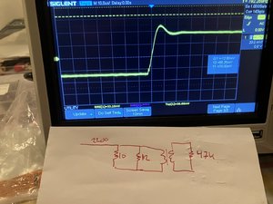
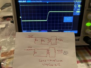
Denne var nyttig..for RC last av sekundær vikling på MC trafo.
info om Menno Vandeveen MC step up
info om Menno Vandeveen MC step up
Sist redigert:


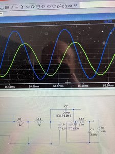


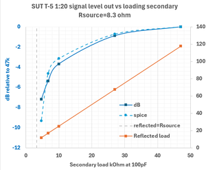

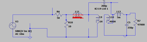
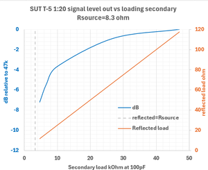

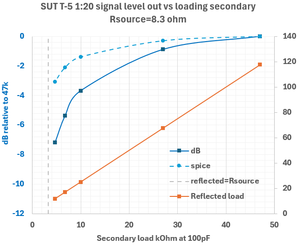
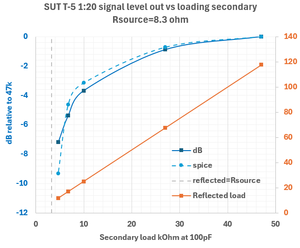


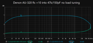
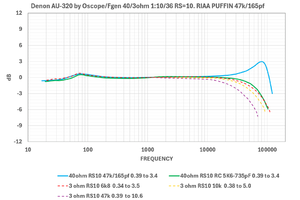
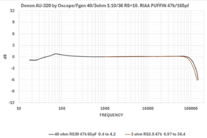
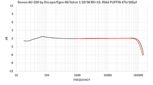
Samlet begge metoder for å teste og beregne SUT loading. SUT step up trafo lastberegingUsing an RC Zobel network on the secondary of an MC step-up transformer can be a useful technique to flatten the frequency response and control resonance peaks. Here’s how you can implement and choose the components for an RC Zobel network:
### Purpose of the RC Zobel Network
The Zobel network (a resistor and capacitor in series) is used to stabilize the impedance seen by the secondary of the transformer, helping to dampen any high-frequency resonances and ensuring a smoother frequency response.
### Steps to Implement an RC Zobel Network
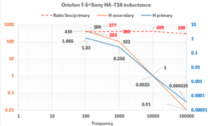
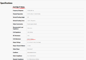
1. **Determine the Inductance of the Secondary Winding**:
- Obtain the inductance value of the secondary winding of your transformer from the manufacturer’s specifications or measure it if possible. This is often given in millihenries (mH).
2. **Calculate the Capacitance**:
- The capacitor in the Zobel network is chosen to resonate with the inductance of the secondary winding at a frequency beyond the audio range (typically above 20 kHz to avoid affecting the audio signal).
- Use the formula:
\[
C = \frac{1}{(2 \pi f)^2 L}
\]
where \( f \) is the target frequency (e.g., 50 kHz) and \( L \) is the inductance.
3. **Calculate the Resistor Value**:
- The resistor value should be approximately equal to the impedance of the secondary winding at the chosen frequency.
- If the secondary impedance at 50 kHz is not directly available, you can estimate it as close to the DC resistance of the secondary winding.
4. **Construct the Network**:
- Connect the calculated resistor and capacitor in series.
- Place this series combination across the secondary winding of the transformer.
### Example Calculation
Suppose the secondary inductance \( L \) is 200 mH, and we target a damping frequency of 50 kHz.
1. **Calculate Capacitance**:
\[
C = \frac{1}{(2 \pi \times 50000)^2 \times 0.2}
\]
\[
C \approx 0.032 \, \mu\text{F}
\]
2. **Calculate Resistor**:
- Assume the impedance of the secondary winding at 50 kHz is around 10 kΩ.
- Use a resistor of approximately 10 kΩ.
3. **Component Selection**:
- Use a high-quality film capacitor (0.033 µF is a standard value close to the calculated 0.032 µF).
- Use a high-precision resistor, 10 kΩ.
### Practical Implementation
- **Install the RC Zobel Network**:
- Solder the 0.033 µF capacitor and the 10 kΩ resistor in series.
- Connect the series combination across the secondary winding terminals of the transformer.
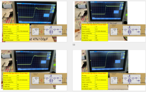
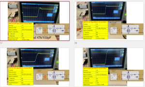
- **Fine-Tuning**:
- You might need to fine-tune the component values slightly to match the exact characteristics of your transformer and system.
- Listen to the changes in sound quality and adjust as necessary.
### Benefits and Considerations
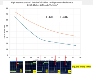
- **Improved Frequency Response**:
- The RC Zobel network will help in flattening the high-frequency response, reducing peaking and providing a more natural sound.
- **Damping Resonances**:
- It effectively damps high-frequency resonances that can cause distortion or harshness.
- **Component Quality**:
- Use high-quality resistors and capacitors to avoid introducing noise or degradation.
Using an RC Zobel network is a technical yet effective way to enhance the performance of your MC step-up transformer, ensuring a balanced and detailed sound reproduction.
 [/
[/


 , var det SUT degaussingen , justeringen av beltet, eller bare dagformen..eller tvungen avholdenhet ? Samma det,jobben venter på mandag.. mer musikk Nuh!


 ampsandsound.com

 www.skunkiedesigns.com


 diyaudioheaven.wordpress.com