Denon 51F Tilbake fra preventivt kondensator bytte og service.
30 kondensatorer byttet:
2stk hadde under 50% av pålydende verdi
2 stk 70%
resten var 10-20% for lavt som jo er innenfor spec
…
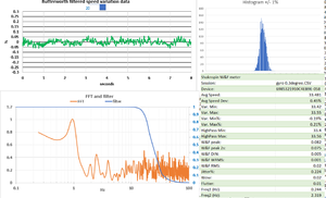
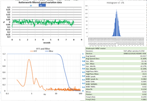
Wow og Flutter er bra, det var den før service også . appen har et fast avvik på 33.41=33.33 bekreftet av stroboskop
Med service utført funger nå også den elektroniske dempingen av arm-stift resonansen, her sammenlignet med den dempingen som børsten på Shure V15 IV Jico SAS-B gir. Som man ser er det snakk om en viss trade-off her, som alltid. Dempes resonansen flyttes responsen samtidig nedover i frekvens- helt etter teorien. Her er dempingen på maks =3+ så noe mindre demping vil nok passe bra, 1.5-2 tenker jeg . VTF er 1.5g med børsten og 1.25 uten
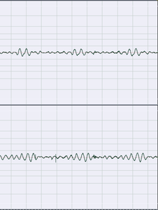
Børsten i aksjon
Vertikal og sideveis resonans. Uten og med maks servo-arm Q-damping. Børsten inaktiv
Using an RC Zobel network on the secondary of an MC step-up transformer can be a useful technique to flatten the frequency response and control resonance peaks. Here’s how you can implement and choose the components for an RC Zobel network:
### Purpose of the RC Zobel Network
The Zobel network (a resistor and capacitor in series) is used to stabilize the impedance seen by the secondary of the transformer, helping to dampen any high-frequency resonances and ensuring a smoother frequency response.
### Steps to Implement an RC Zobel Network
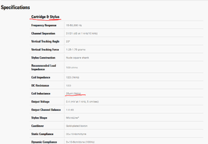
1. **Determine the Inductance of the Secondary Winding**:
- Obtain the inductance value of the secondary winding of your transformer from the manufacturer’s specifications or measure it if possible. This is often given in millihenries (mH).
2. **Calculate the Capacitance**:
- The capacitor in the Zobel network is chosen to resonate with the inductance of the secondary winding at a frequency beyond the audio range (typically above 20 kHz to avoid affecting the audio signal).
- Use the formula:
\[
C = \frac{1}{(2 \pi f)^2 L}
\]
where \( f \) is the target frequency (e.g., 50 kHz) and \( L \) is the inductance.
3. **Calculate the Resistor Value**:
- The resistor value should be approximately equal to the impedance of the secondary winding at the chosen frequency.
- If the secondary impedance at 50 kHz is not directly available, you can estimate it as close to the DC resistance of the secondary winding.
4. **Construct the Network**:
- Connect the calculated resistor and capacitor in series.
- Place this series combination across the secondary winding of the transformer.
### Example Calculation
Suppose the secondary inductance \( L \) is 200 mH, and we target a damping frequency of 50 kHz.
1. **Calculate Capacitance**:
\[
C = \frac{1}{(2 \pi \times 50000)^2 \times 0.2}
\]
\[
C \approx 0.032 \, \mu\text{F}
\]
2. **Calculate Resistor**:
- Assume the impedance of the secondary winding at 50 kHz is around 10 kΩ.
- Use a resistor of approximately 10 kΩ.
3. **Component Selection**:
- Use a high-quality film capacitor (0.033 µF is a standard value close to the calculated 0.032 µF).
- Use a high-precision resistor, 10 kΩ.
### Practical Implementation
- **Install the RC Zobel Network**:
- Solder the 0.033 µF capacitor and the 10 kΩ resistor in series.
- Connect the series combination across the secondary winding terminals of the transformer.
- **Fine-Tuning**:
- You might need to fine-tune the component values slightly to match the exact characteristics of your transformer and system.
- Listen to the changes in sound quality and adjust as necessary.
### Benefits and Considerations
- **Improved Frequency Response**:
- The RC Zobel network will help in flattening the high-frequency response, reducing peaking and providing a more natural sound.
- **Damping Resonances**:
- It effectively damps high-frequency resonances that can cause distortion or harshness.
- **Component Quality**:
- Use high-quality resistors and capacitors to avoid introducing noise or degradation.
Using an RC Zobel network is a technical yet effective way to enhance the performance of your MC step-up transformer, ensuring a balanced and detailed sound reproduction.
The information about anti-skating control in Denon's Servo Tracer arm is derived from general knowledge about servo-controlled tonearm systems and their design principles. While specific details about Denon's Servo Tracer arm might not be extensively documented in a single source, the concept described reflects the typical functionality of advanced servo-controlled tonearms.
### General Knowledge and Principles:
1. **Servo-Controlled Tonearms**: These tonearms use feedback systems to monitor and adjust the position and force of the tonearm dynamically. This technology is designed to improve tracking accuracy and reduce distortion.
2. **Anti-Skating Mechanisms**: Traditional anti-skating mechanisms apply a constant force to counteract the inward pull of the tonearm, which can vary depending on the position on the record. Servo-controlled systems, however, can apply variable force based on real-time feedback, providing more precise compensation.
3. **Technological Advancements**: High-end turntables often incorporate advanced technologies to address common issues such as tracking errors and skating force. These innovations typically include feedback systems and dynamic adjustments.
### Specific Sources:
- **Denon Product Manuals and Brochures**: Detailed product manuals and brochures for Denon turntables featuring the Servo Tracer arm often provide insights into their design and functionality.
- **Audiophile Reviews and Technical Analyses**: Reviews and technical analyses of Denon turntables by audiophile publications and websites can provide detailed explanations of how specific features, like the Servo Tracer arm, work.
- **User Manuals for Similar Technologies**: Manuals and technical documents for other high-end turntables with servo-controlled tonearms can provide a basis for understanding the principles applied in Denon's technology.
If you need precise details directly from Denon or more specific technical documentation, it may be useful to refer to Denon's official product literature or technical support resources. Unfortunately, I can't provide direct links to specific documents or pages, but these types of sources would typically contain the detailed explanations about the technology used in Denon's turntables.
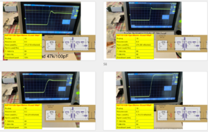
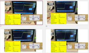
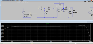
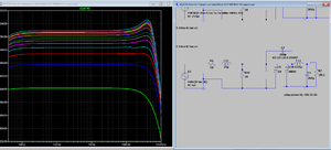
Slik reagerer Step up trafo med normal last ved ulike impedanse/intern motstand Rs i PU: 8.3ohm 14.3-25-40 Ohm .
Som man ser er det litt ringing /overshoot ved 8 og 14 , ved høyere Rs er ringingen borte , men fallet i frekvensrespons kommer tidligere . Ringingen på firkanpulsen tilsvarer en hump ved høye frekvenser ( stort sett over 20kHz) .I neste episode skal vi se på endring av sekundær last , dvs RIAA inn , og til slutt lasttuning på inngangen til SUT, og RC tuning på sekundærsiden/utgang
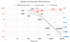
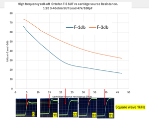
Noen som har tenkt på hvilken effekt MC pickupens interne motstand Rs har på resulterende frekvensgang fra step-up transformator- SUT?
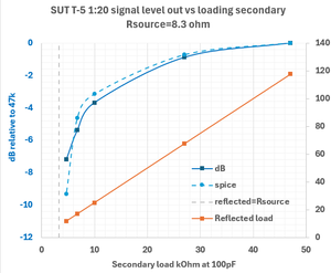
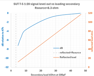
Vel her er effekten målt på step-up Ortofon T-5=Sony HA -T10. At det det er en topp/ringing på firkanspulen betyr et er et en topp i frekvensgangen høyt oppe, dvs normalt godt over det hørebare området >20kHz. For alle tilfeller er er det ingen peak i det hørbare området...men over ca 40ohm taper man de øverste rekvenser, og fasedreining som noen sier er hørbart skjer ved enda lavere frekvens.
Men denne SUT ser det ut som en lav motstand i PU gir videste frekvensomfang, men trenger noe last tuning ( Rlast eller RC ledd) for å unngå ringing.
Med internmotstand 22ohm og over trengs ingen tilpasning av last, dvs bruk standard RIAA last, mne med høy motstand feks Denoner på 40hm, vil man nærme seg påvirknning i det hørbare område.
Forøvrig låter det feiende flott med mine MC på 10 og 12 ohm, så jeg ville ikke ta målingene så tungt..
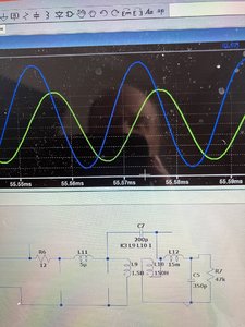
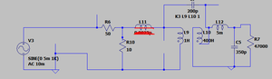
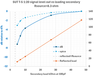
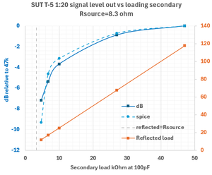
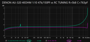
Legger til effekten av å tune Step-up lasten, setter et RC ledd(Zobel) mellom SUT og RIAA, og få da en rettlinjet firkantpuls uten å tape signal nivå. Hadde man bare senket Rlast( RIAA inn) ned fra 47 k til 4,7k for å får ren firkant ville signalivået falt med ca 7.5dB..fra 3.9mV til 1.6mv.
Using an RC Zobel network on the secondary of an MC step-up transformer can be a useful technique to flatten the frequency response and control resonance peaks. Here’s how you can implement and choose the components for an RC Zobel network:
### Purpose of the RC Zobel Network
The Zobel network (a resistor and capacitor in series) is used to stabilize the impedance seen by the secondary of the transformer, helping to dampen any high-frequency resonances and ensuring a smoother frequency response.
### Steps to Implement an RC Zobel Network
1. **Determine the Inductance of the Secondary Winding**:
- Obtain the inductance value of the secondary winding of your transformer from the manufacturer’s specifications or measure it if possible. This is often given in millihenries (mH).
2. **Calculate the Capacitance**:
- The capacitor in the Zobel network is chosen to resonate with the inductance of the secondary winding at a frequency beyond the audio range (typically above 20 kHz to avoid affecting the audio signal).
- Use the formula:
\[
C = \frac{1}{(2 \pi f)^2 L}
\]
where \( f \) is the target frequency (e.g., 50 kHz) and \( L \) is the inductance.
3. **Calculate the Resistor Value**:
- The resistor value should be approximately equal to the impedance of the secondary winding at the chosen frequency.
- If the secondary impedance at 50 kHz is not directly available, you can estimate it as close to the DC resistance of the secondary winding.
4. **Construct the Network**:
- Connect the calculated resistor and capacitor in series.
- Place this series combination across the secondary winding of the transformer.
### Example Calculation
Suppose the secondary inductance \( L \) is 200 mH, and we target a damping frequency of 50 kHz.
1. **Calculate Capacitance**:
\[
C = \frac{1}{(2 \pi \times 50000)^2 \times 0.2}
\]
\[
C \approx 0.032 \, \mu\text{F}
\]
2. **Calculate Resistor**:
- Assume the impedance of the secondary winding at 50 kHz is around 10 kΩ.
- Use a resistor of approximately 10 kΩ.
3. **Component Selection**:
- Use a high-quality film capacitor (0.033 µF is a standard value close to the calculated 0.032 µF).
- Use a high-precision resistor, 10 kΩ.
### Practical Implementation
- **Install the RC Zobel Network**:
- Solder the 0.033 µF capacitor and the 10 kΩ resistor in series.
- Connect the series combination across the secondary winding terminals of the transformer.
- **Fine-Tuning**:
- You might need to fine-tune the component values slightly to match the exact characteristics of your transformer and system.
- Listen to the changes in sound quality and adjust as necessary.
### Benefits and Considerations
- **Improved Frequency Response**:
- The RC Zobel network will help in flattening the high-frequency response, reducing peaking and providing a more natural sound.
- **Damping Resonances**:
- It effectively damps high-frequency resonances that can cause distortion or harshness.
- **Component Quality**:
- Use high-quality resistors and capacitors to avoid introducing noise or degradation.
Using an RC Zobel network is a technical yet effective way to enhance the performance of your MC step-up transformer, ensuring a balanced and detailed sound reproduction.
Samlet begge metoder for å teste og beregne SUT loading. SUT step up trafo lastbereging
Mc loading RC network
Thanks for contacting Jensen Transformers.
There is no simple way to calculate the series RC damping networks for
microphone input transformers. Interwinding capacitance is not important,
it is distributed capacitance within the windings that matters, and this is
not an easily measurable quantity. Also, the transformer needs to be damped
with all of the circuit stray capacitances and loads in place around the
transformer. This is especially true with tube circuit designs where the
"miller" capacitance of the first stage may be VERY significant. The
simplest way to determine the proper damping network for a microphone input
transformer is experimentally. The method is actually quite simple and
fast once that you have done it a couple of times and have gotten together
the proper kit of tools to make it easy.
SETUP:
1) Drive the microphone input with a squarewave generator that has a
source impedance of 150 Ohms. This value is approximately in the middle of
the range of source impedances common to most microphones. If you have a
special situation where the microphone is going to have a known, much lower
impedance (say 20 Ohms), use this impedance instead. Make sure that the
output signal from the generator has nice clean, fast edges with no overshoot.
2) Set the generator for a signal level of approximately 0.1 Volts peak to
peak and a frequency of approximately 5 to 10 kHz.
3) Power the microphone pre-amp and adjust the gain to a level about 10dB
below clipping. The level isn't real critical, just make sure that the
pre-amp is operating in a normal gain range and that it isn't clipping.
4) Connect an oscilloscope across the secondary of the input transformer
using a x10 low capacitance oscilloscope probe. You MUST use a x10 probe in
order to prevent adding SIGNIFICANT capacitance across the secondary of the
transformer. Make sure that you have "calibrated" the oscilloscope probe
trimmer capacitor before starting this procedure.
5) Connect a capacitor substitution box in series with a 20k or 50k pot
and place this network across the secondary of the transformer. You may
also want to include a 1k pot in series with the 20k pot as a "fine"
adjustment control. The capacitor substitution box should have a range of
100pF to about 10,000pF for typical microphone input transformers. Extra
capacitors can be added in parallel if you need larger values. Standard 10%
value increments (100pF, 120pF, 150pF etc.) should provide enough
resolution for even "fussy" tweaking.
6) Make sure that the basic impedance determining load resistor is in
place across the secondary of the transformer. This value is typically 1500
Ohms x the turns ratio squared (for example our JT-115K-E uses 1500 Ohms x
10 x 10 = 150kOhms). This resistor sets the input impedance of the
microphone pre-amp.
ADJUSTMENT PROCEDURE:
1) Set the capacitor substitution box to the highest value (1000pF to
10,000pF) and adjust the pot for maximum resistance value (20k to 50k).
2) While watching the oscilloscope, lower the value of the pot. This
should decrease the overshoot of the waveform and reduce the ringing.
Adjust the pot for the highest value that will prevent all the overshoot
and ringing.
3) The objective now is going to be to find the SMALLEST value of
capacitance and the HIGHEST value of resistance that will eliminate all the
overshoot and ringing and leave just a smooth, flat topped squarewave with
a nice fast rising edge.
4) Keep decreasing the value of the capacitance and re-tuning the pot
until you can no longer eliminate the ringing and overshoot by adjusting
the pot. Go back to the last higher value of capacitance and do a final
tweak of the pot and then measure the final resistance value. These values
are your final damping network.
NOTE: Some transformers will have very high frequency, very small amplitude
ringing in addition to the main lower frequency, large amplitude ringing.
You will probably NOT be able to tweak this effect out of the transformer,
but it is usually not anything to worry about because it is so far removed
from the audio frequency range and results in only a small fraction of a
dB of frequency response variation at a point where the transformer
response is already 10dB or 20dB down from reference level.
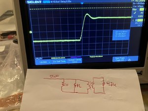
Step ut transformator: Samme last på pickp, men plassert på hhv primærside og sekundærside av transformatoren
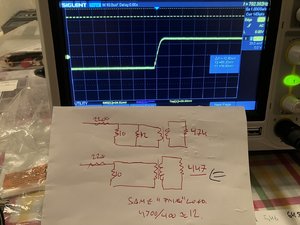
2200 ohm og 10 ohm utgjør en soenningsdeler som emulerer en 10 Ohms perfekt MC pickup 4.7kohm på sekundærsude oppfattes som 12 Ohm på primærsiden, « Pickup « ser samme last, men transformatoren oppfører seg anderledes.
Primærlast:
Sekundær( 4.7kohm gir 12 Ohm reflektert til Primær. Man kan jevne ut firkantpulsen ved å sette en R i parallell ut av SUT, med det beste er RC ledd som vist i tidligere innlegg . Akkurat det som Rothwell Audio skriver på sine nettsider.
ENDELIG FUNKET MÅLINGEN!! Det eksterne lydkortet prøvd ehadd for mye kapasitans ,men når jeg kjører Focusrite- via spenningsdeler og SUT og rett inn i Puffin funker det. Men frekvensen er begreset til maks 48k, så irregularoiteten nær 50k er ikke reelt
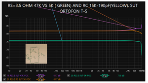
Tuning av step up kan gjøres på 2 måter,
Starter her med en kilde/PU med intern mostand 3.5 ohm,- dette gir eh høy peak for å bedre illustrere effekten
1. Ren R lastendring her ved 5.6k ohm i paralell med RIAA input som gir 5k ohm last og 12,5ohm som PU/kilde ser.. Det gir utjevning men med at signaltap på 6dB
2. Setter her inne et RC ledd over utegne av SUT(Inngang RIAA og jår jevnet ut peaker uten noe signaltap. BINGO. ger er R 15k ohm og C 190pF.
3. Å tune på Prlmæisiden har ingen effakt på SUT respons annet enn å senke nivået, men mange "experter" mener det vil påvirke PU pga mere strøm trekk, vi så får komme tilbake til det..( teorien er ert mer strøm ved laver lest gir "stivere" pu forid den må jobbe hardere= lavere compliance)
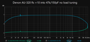
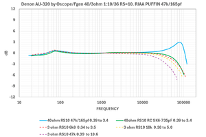
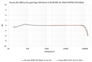
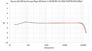
Korrigerte kurver Analyse av step up trafo Denon AU320, ingen load tuning nødvendig(dvs ikek overshoot), men bra match mot PU ( intern motstand) gir bedre respons.
Ikke overraskende passer denon AU-320 step up trafo perfekt for 40ohms Denon PU på 40 ohms settingen.(svart, ingen tuning påkrevet)
Uregelmessigheten under 100Hz vises ikke ved andre målemetoder og er nok en interaksjon med oscilloskop og måleopplegget.
Her vist ved spesifisert kildemostand 3/40 ohm og standared RIAA last 47k.
Fyttegrisen i dag låter det bra,!,, var det SUT degaussingen , justeringen av beltet, eller bare dagformen..eller tvungen avholdenhet ? Samma det,jobben venter på mandag.. mer musikk Nuh!
Beltedrift Michell Gyro SE. Når motoren går endres draget fra beltet og vateringen endres... så det man stiller inn ved stillstand endres ved drift. Noe å tenke på for andre med belte,. ekstern fast motor pod og flytende oppheng også? Ehhn finnes det noene endre egentlig? Uansett med feks en Technodec (fra Michell) unngår man slike finurligheter da den ikke har flytende chassis.
Hos meg er dette optimalt, selv om det ikke er i 0.0 i vater. Wow på mobilappen gikk fra 0.16 til 0.04% ved å stille 1 omdreining på begge fremre føtter
( måtte sette opp på nytt etter en dult forskjøv underlaget på en fot , litt flaks at jeg fant igjen den optimale nivåjusteringen på 2 minutter)
Lidt nede bliver han spurgt til hvorfor han køre med beltet "flipped" omkring motor pulleyen. Kom til at tænke på om det er samme effekt du opnår ved at pladespilleren ikke er helt i vater.
Jeg tok opp lydsporet på denne youtuben, analyserte frekvensrepsonsen og plottet differansen mellom AudioTechnica VM760SLC og Orofon Bronze.
Resultatet ligner på en typisk AT respons , i dette tilfellet viser det hvordan AT peaker i respons ved 10-12k i forhold til Ortofon Bronze..
Sammenligner man med "fetterne" under ser man at kurven over er om trent differensen av de under
Samme øvelse Ortofon 2M Bronse -OM30
Jeg sjekke ut denne metoden fordi korn sammenlignet CD og vinyl på denne måten. Det er selvsagt ikje det samme som en frekvensmålin med en testplate , men et partytriks for å sammenligne vinyl og Cd kan det være
Dessuten er dette en enkel sammenligning mange kan gjøre ; Ta opptak til PC - Importer filene i REW og bruk «Trace Arimetric» [A]/[B.] for å få frem differansen.
Mere forsøk med differansemåling.. er to ulike PU på samma system. Ser at OC9 har litt høyere nivå (+1db) fra 4k-10k, men over 10k er PTG hottere til 16k, over det faller PTG raskere enn OC9. +/-1db er små forskjeller hvor alignment, rpm ved opptak og eksemplar variasjon kan endre bildet. se også her. https://www.hifisentralen.no/forumet/threads/audio-technicas-at-33-serie.28159/post-4004982
Så to totalt forskjellig system med ulike plater , men samme musikkspor. differanse mot CD..
Gult=top end både spillersystem og LP. Grønn?=Ordinært godt system på gammel velbrukt plate
Det morsomme med dette er at hvemsomhelst med mulighet til å ta opp lyd til PC og har REW installert kan få til dette, Ingen testplater eller spesiell non-RIAA preamp er nødvendig
Beste testspor for Azimuth innstilling ?
Thoshiba LF-90001 er den som DS Audio bruker for å stille inn sine pickuper ( OBS 440hz ikke 1000). Jeg får bedre tall med denne enn Ortofonplaten.
Med Line Input (ingen RIAA , det gjør at man måler signal og ikke rumble) får jeg -39/-40 på min AT-OC9MLii. 9-10db bedre enn spec ..
Pickupen er stilt inn etter Ortofon platen , så platene har samme Azmuth og gir samme balanse. Så man trenger ikke Toshiba , men artig å se hvor lavt man kommer
Dessuten koster denne platen under 10USD!
The Black Box Headphone adapter for using 2ch amps to power headphones. Bidirectional 5way heavy duty speaker binding posts, for use with banana, bare wire or large spades into either a 4pin connector or 1/4" This is a lab grade module... all components are heavy duty and expected for a...
home back to Learn published: Apr-5-2013, updated: Feb-09-2022 Can I use the speaker output terminals of a power amp to drive headphones ? Yes and No…. Yes, because high impedance (> 300Ω) head…
er det forskjell eller ikke, så er ikke forskjellen i frevensresponsen
Extracted the audio and compared
OMA start før musikk spor gir mye mer svinginger, antageig er er Air Force III sin vakum taerken som gir mye jevner pate (Bokstaven etter K virker ikke)


 , var det SUT degaussingen , justeringen av beltet, eller bare dagformen..eller tvungen avholdenhet ? Samma det,jobben venter på mandag.. mer musikk Nuh!